
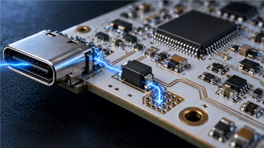
A transient voltage suppressor, or TVS diode, protects sensitive electronics from short overvoltage events that may enter through power rails, connectors, communication lines, or inductive loads.
This simple description is useful, but it leaves out the engineering details that determine whether protection actually works: the difference between stand-off, breakdown, and clamping voltage; the surge waveform; dynamic resistance; package inductance; line capacitance; PCB placement; and the impedance of the ground return. This guide explains the complete protection path and turns it into a practical BOM and RFQ checklist.
What Is a TVS Diode?
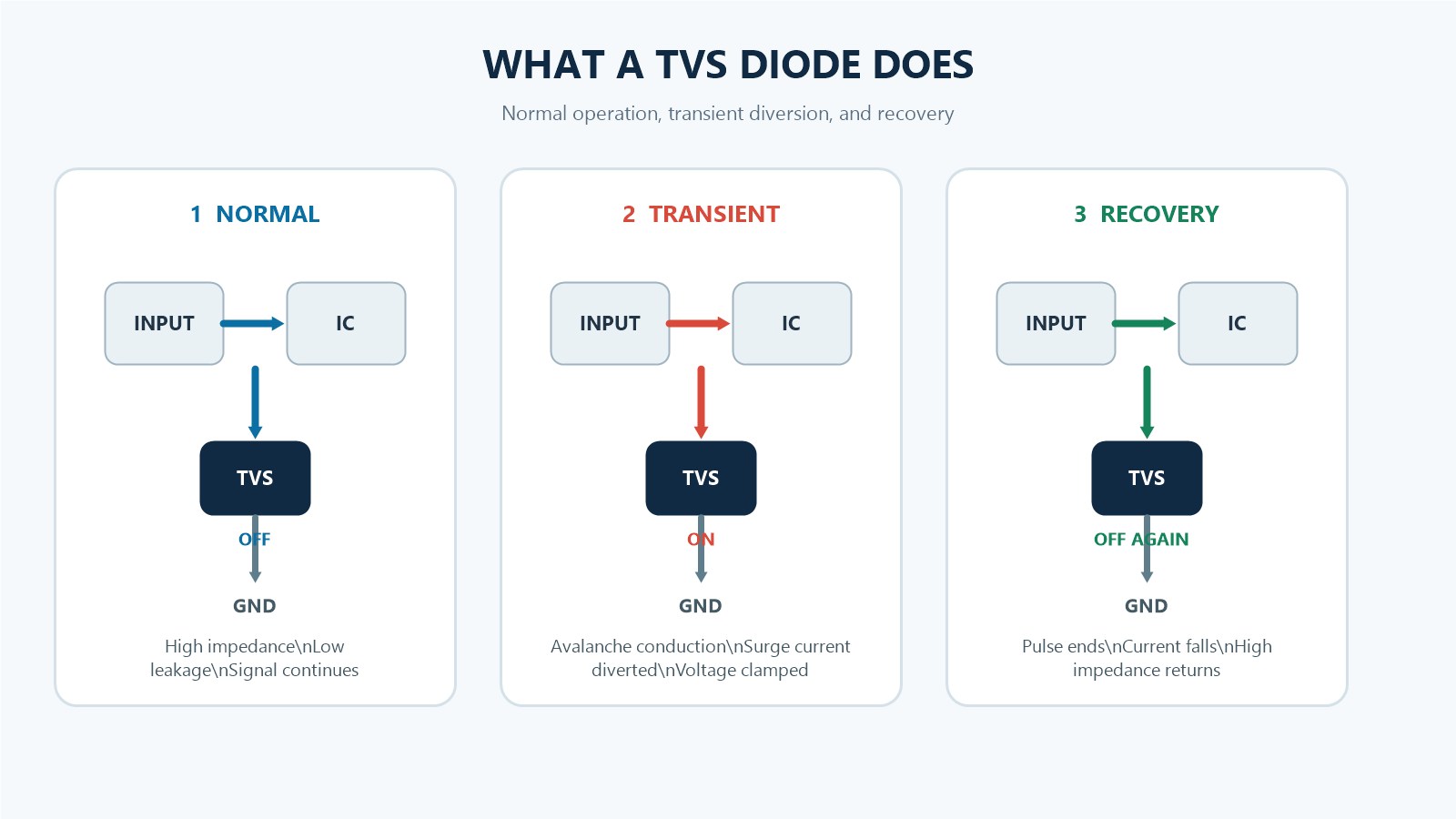
A TVS diode is a semiconductor protection device designed to respond to transient overvoltage. It is normally connected in parallel between the line being protected and a return node such as ground. Unlike a series fuse, the TVS diode does not normally carry the load current.
TVS devices use controlled avalanche or forward conduction to create a low-impedance path during a surge. They are available as larger discrete parts for power rails and as low-capacitance single-line or multi-line arrays for interfaces. The correct family depends on the transient source, the protected line, and the test waveform.
How Does a TVS Diode Work?
1. Below the working peak reverse voltage
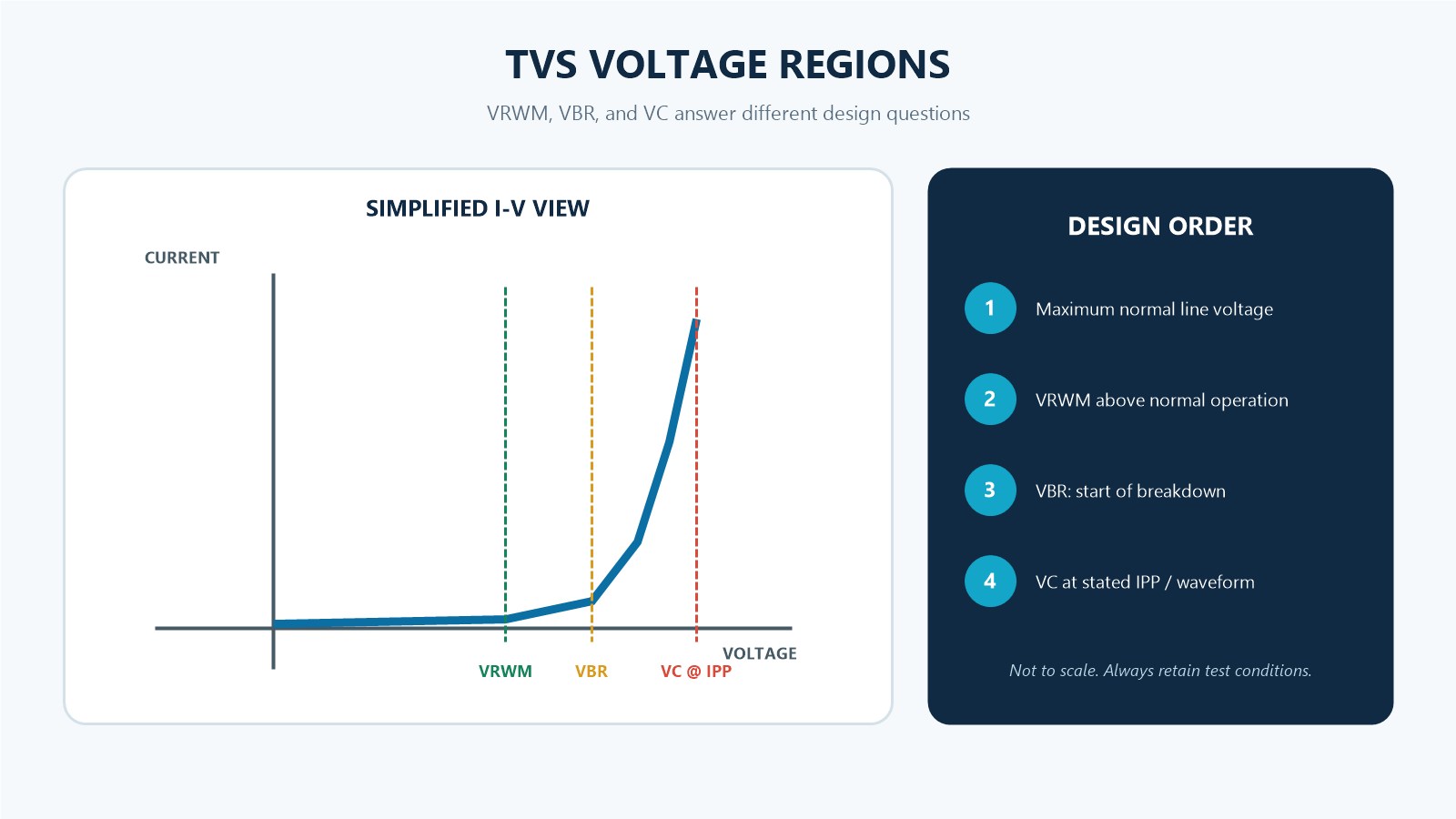
When the line remains below the specified working peak reverse voltage, usually shown as VRWM or VR, a reverse-connected TVS diode has high impedance. Only specified leakage current flows. For signal lines, its capacitance is not zero, so the designer must still check signal integrity.
2. At the breakdown region
When reverse voltage reaches the breakdown voltage VBR under the datasheet test condition, avalanche current begins to increase sharply. VBR marks the start of significant conduction; it is not the maximum voltage that the protected IC will see during a real surge.
3. At the specified surge current
As surge current rises, the TVS voltage rises above VBR. The datasheet’s clamping voltage VC is specified at a defined peak pulse current IPP and waveform. The protected device therefore sees a residual clamped voltage, not zero volts. PCB trace and return-path inductance can add an additional overshoot before the TVS fully controls the node.
Where Does the Transient Current Go?
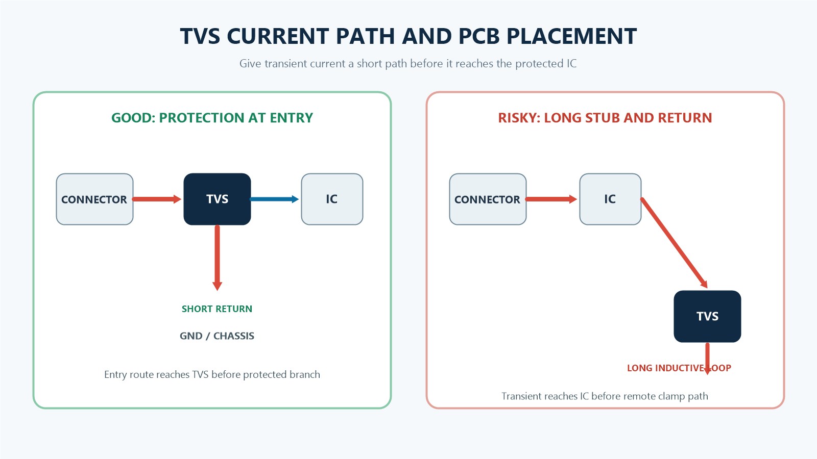
The phrase “the TVS absorbs the surge” can hide the most important system question: where does the current flow? A TVS diode creates a shunt path. For that path to be effective, transient current must reach the TVS before it reaches the protected IC, then return through a short, low-inductance connection.
A practical current path is:
- The transient enters through a connector, cable, exposed terminal, or switching node.
- The board route reaches the TVS protection point before branching toward the protected circuit.
- The TVS conducts and redirects current into the ground, chassis, or designated return network.
- The remaining clamped voltage propagates toward the protected component.
What Transients Can a TVS Diode Address?
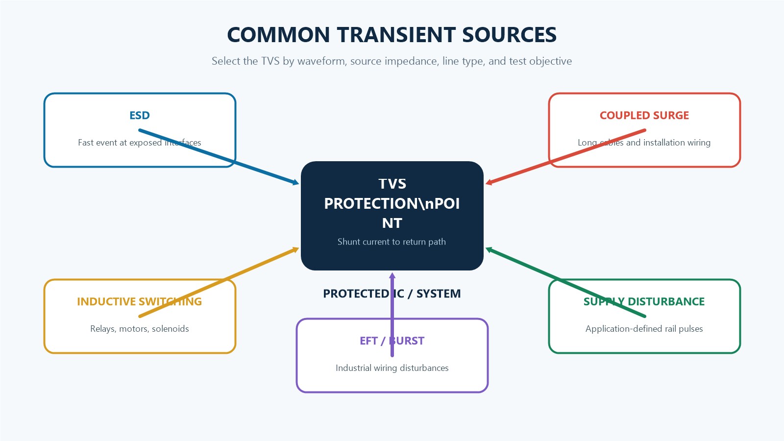
TVS diodes are used against short-duration electrical overstress, but the required device is application-specific. Common sources include:
- Electrostatic discharge: fast events entering through USB, Ethernet, buttons, sensor leads, or exposed metal.
- Inductive switching: voltage generated when current through a relay, solenoid, motor, or other inductance changes quickly.
- Electrical fast transients: bursts coupled onto industrial power and signal wiring.
- Coupled surge energy: disturbances associated with long cables, installation wiring, or nearby lightning activity.
- Vehicle and supply disturbances: application-defined pulses on automotive or industrial rails.
The words ESD, surge, and transient are not interchangeable test specifications. A part selected only by voltage may pass one waveform and fail another because pulse width and source impedance change the energy delivered to the diode.
Which TVS Diode Parameters Matter?
| Parameter | What it tells you | Design check |
|---|---|---|
| VRWM / VR | Highest stated reverse stand-off voltage for the blocking region. | Keep it above the maximum continuous line voltage, including tolerance and normal overshoot. |
| VBR | Breakdown voltage measured at a specified test current. | Do not use VBR as if it were the surge clamping voltage. |
| VC | Clamping voltage at a stated IPP and waveform. | Compare it with the protected circuit’s tolerable transient voltage, including layout overshoot. |
| IPP / PPP | Peak pulse current and peak pulse power under stated waveform conditions. | Match the actual or compliance-test waveform; headline wattage alone is insufficient. |
| RDYN | Voltage rise per increase in surge current in the clamping region. | Lower dynamic resistance generally helps hold VC down as current increases. |
| Capacitance | Electrical loading added to the protected line. | Critical for USB, Ethernet, RF, high-speed serial, and precision analog interfaces. |
| IR | Leakage current at the specified reverse voltage. | Check high-impedance, battery, and precision sensing circuits, including temperature effects. |
| Polarity | Unidirectional or bidirectional behavior. | Match the line’s normal positive/negative swing and surge polarity. |
| Package | Thermal, inductive, assembly, and footprint constraints. | Confirm package code, land pattern, height, qualification, and assembly process. |
Unidirectional or Bidirectional?
A unidirectional TVS normally uses avalanche conduction in one polarity and ordinary forward conduction in the opposite polarity. It is commonly considered for DC rails where the voltage polarity is fixed. A bidirectional TVS has more symmetrical behavior and may be appropriate when the protected node has bipolar operation or an AC waveform.
The choice cannot be made from the name alone. Confirm the normal voltage excursion, allowable negative voltage, circuit reference, and the manufacturer’s polarity convention. For a fuller comparison of TVS devices and interface-focused ESD protection parts, see our TVS diode vs ESD protection diode selection guide.
What a TVS Diode Does Not Do
- It does not regulate a supply continuously like a normal power regulator.
- It does not replace a fuse, circuit breaker, current limiter, or thermal protection device.
- It does not automatically protect against sustained overvoltage if the event exceeds its time and power ratings.
- It does not guarantee a safe IC voltage just because VRWM matches the rail.
- It does not compensate for a long, inductive PCB path or a poor ground return.
- It does not make signal-line capacitance irrelevant.
If a sustained fault causes the TVS to conduct continuously, the device may overheat and fail. Failure mode is not universally guaranteed to be open or short, so system protection should not depend on one assumed outcome. Power-rail designs commonly coordinate the TVS with upstream impedance, a fuse, or another disconnect element.
A Practical Selection Sequence
Consider a connector-fed DC rail. The exact values depend on the application, but the engineering sequence is consistent:
- Define the maximum legitimate steady-state voltage at the connector, including tolerance and expected operating variation.
- Select a VRWM above that level so the TVS does not conduct during normal operation.
- Define the transient waveform, source impedance, peak current, pulse duration, repetition, and applicable standard.
- Review VC at the relevant current, not only VBR.
- Confirm that the downstream circuit can tolerate the expected clamped voltage plus layout-induced overshoot.
- Check pulse power, temperature derating, repetition rate, polarity, package, and qualification requirements.
- Place the TVS near the entry point and design a short return path.
- Validate the assembled board under the intended test method.
B2B BOM and RFQ Checklist
For sourcing or replacement review, “TVS diode” is not a complete specification. Include the following:
- Manufacturer and exact part number, including suffix.
- Unidirectional or bidirectional configuration.
- VRWM, VBR range and test current, VC and its IPP/waveform.
- Peak pulse power/current and waveform definition.
- Capacitance and test conditions for signal-line devices.
- Leakage limits and operating temperature.
- Package, footprint, height, reel quantity, and moisture sensitivity information where applicable.
- Required qualification or compliance evidence; do not infer it from a similar series.
- Substitution limits and which parameters may not change.
Frequently Asked Questions
Does a TVS diode conduct during normal operation?
A correctly selected reverse-connected TVS diode normally has high impedance and only specified leakage current below VRWM. It still adds capacitance to the line.
Is a TVS diode connected in series or parallel?
It is normally connected in parallel from the protected line to the chosen return path. It shunts transient current rather than carrying normal load current in series.
Is clamping voltage the same as breakdown voltage?
No. VBR is measured at a defined breakdown test current. VC is the residual voltage at a specified, usually much higher, pulse current and waveform.
Can a TVS diode replace a fuse?
No. A fuse interrupts excessive current over its operating time. A TVS diode limits short overvoltage pulses. Many power-input designs use coordinated overvoltage and overcurrent protection.
Where should a TVS diode be placed?
Place it close to the transient entry point, with a short route from connector to TVS and a short, low-inductance return. Route the protected circuit after the protection point.
How do I know whether a TVS diode is suitable for a high-speed line?
Check total capacitance, package parasitics, working voltage, clamping performance, and signal-integrity data for the specific interface. A power-rail TVS is not automatically suitable for USB, Ethernet, or RF.
Engineering References
- Toshiba: How TVS diodes work
- Toshiba: TVS diode electrical characteristics
- STMicroelectronics: Transient voltage suppressors
- STMicroelectronics AN5887: TVS operating behavior
- Littelfuse: Application hints for TVS circuits
Need Help Matching a TVS Diode to Your BOM?
Send the exact part number or the line voltage, transient waveform, package, capacitance, and qualification requirements. ApexComponent can review sourcing requirements and potential alternatives without assuming undocumented compatibility.
Upload your BOM or send an inquiry · Browse TVS diode categories