1.Introduction: Why Do Electronic Devices Need a Bridge Rectifier?
Definition of a Bridge Rectifier
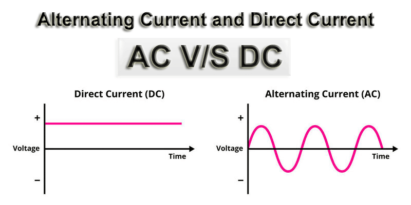
A Bridge Rectifier is a core component in AC-to-DC conversion. It uses four diodes arranged in a bridge configuration to convert alternating current into a unidirectional output.
2.Basic Structure of a Bridge Rectifier
Historical Background (Brief)
The bridge rectifier is also known as the Graetz Bridge:
Concept proposed by Polish engineer Karol Pollak
Popularized by German physicist Leo Graetz
Hence, it is often referred to as a Graetz Rectifier in engineering contexts.
Basic Configuration
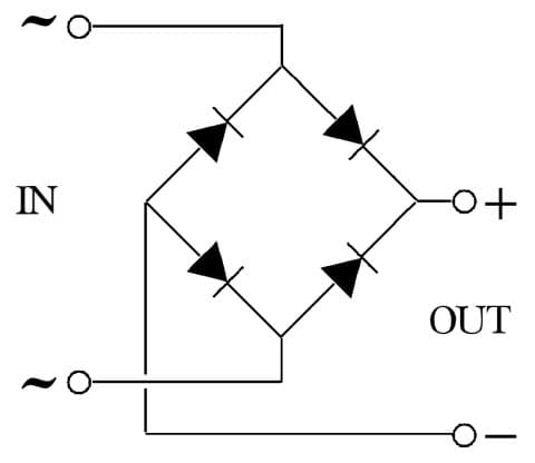
A standard bridge rectifier consists of:
Component
Quantity
Function
Diodes
4
Control current direction
AC Inputs
2
Connect to AC source
DC Outputs
2
Provide rectified output
Typical terminal markings:
~ → AC input
+ → Positive output
- → Negative output
3.How It Works
1. Role of the Diode
A diode functions as a one-way valve:
Forward bias → Conducts
Reverse bias → Blocks
The bridge rectifier uses this property to automatically select the correct current path.
2. Operating Principle
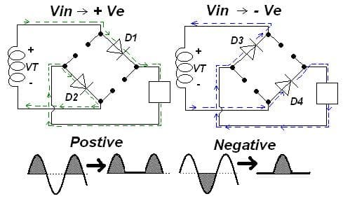
(1) Positive Half-Cycle
Top-left and bottom-right diodes conduct
Current flows through the load → Direction A
(2) Negative Half-Cycle
Top-right and bottom-left diodes conduct
Current still flows through the load → Direction A (unchanged)
Key Insight
Regardless of input polarity reversal, the output current direction remains constant
This is the essence of full-wave rectification.
3. From Pulsating to Smooth DC
After rectification, the output is:
Unidirectional
But still fluctuating (pulsating DC)
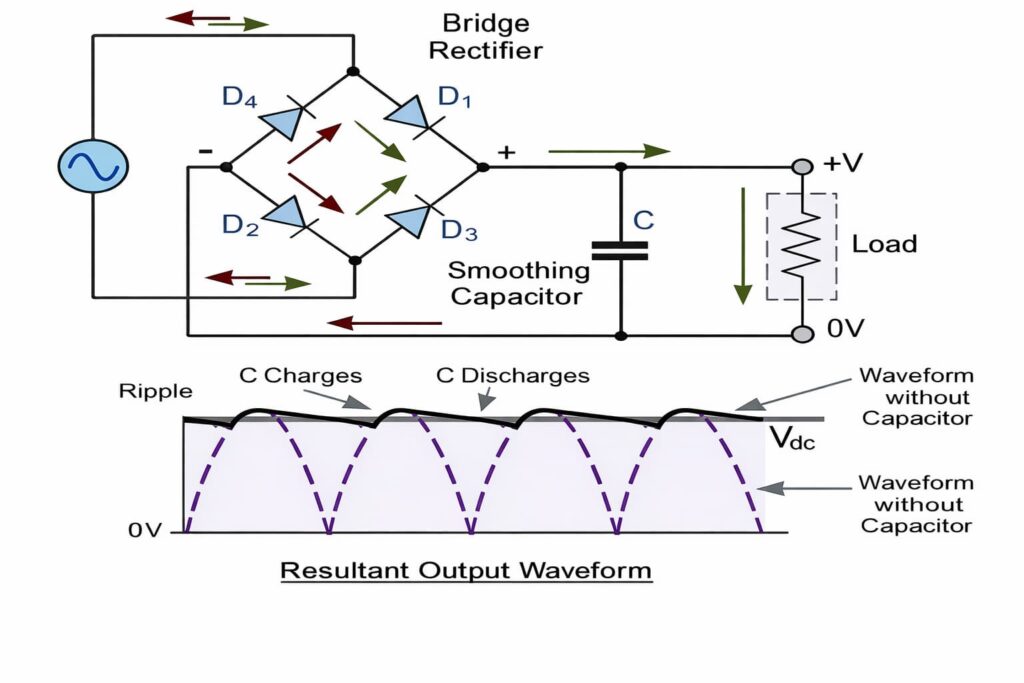
To stabilize it, a filter capacitor is used.
Capacitor Function
Charges when voltage rises
Discharges when voltage drops
Result: Output becomes a smoother DC voltage with reduced ripple
4.Why Bridge Rectification Is the Industry Standard
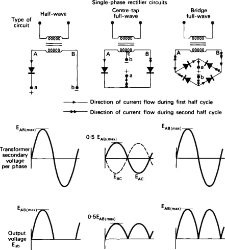
1. Compared to Half-Wave Rectification
Parameter
Half-Wave
Bridge (Full-Wave)
Utilization
50%
100%
Output Stability
Poor
Better
Applications
Simple circuits
Mainstream power supplies
Bridge rectification doubles efficiency.
2. Compared to Center-Tapped Rectification
Parameter
Center-Tapped
Bridge
Transformer
Complex
Simple
Cost
Higher
Lower
Size
Larger
Smaller
Bridge rectifier does not require a special transformer.
3. Single-Phase vs Three-Phase
Type
Application
Single-phase
Consumer electronics, adapters
Three-phase
Industrial systems, motor drives
Three-phase rectification provides smoother output and is suitable for high-power systems.
5.Real-World Applications
1. Consumer Electronics
Phone chargers
Power adapters
Household appliances
Rectification is always the first step after connecting to AC power.
2. Industrial Systems
Motor drives
Electroplating equipment
UPS systems
These applications require higher current capacity and stability.
3. Advanced Applications
EV charging stations
Solar inverters
Energy storage systems
The bridge rectifier acts as the entry point of energy conversion.