
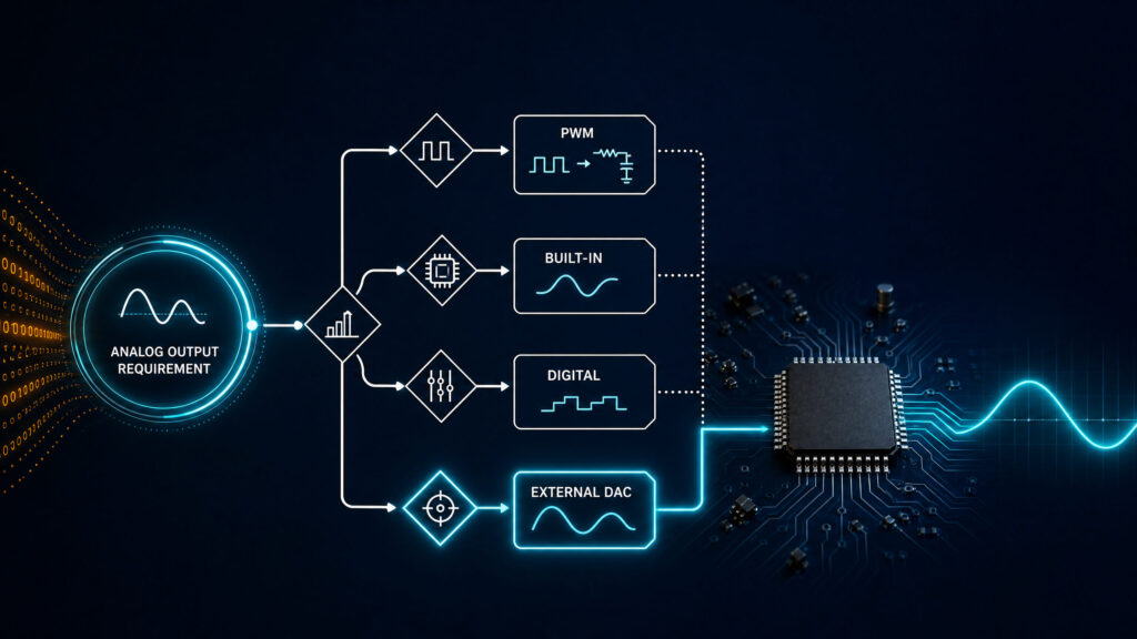
You need a DAC IC when your circuit must create a controlled analog voltage or current from digital code, and when a filtered PWM signal, a built-in microcontroller DAC, or a fully digital interface cannot meet the required accuracy, noise, response time, channel count, or output behavior. For sourcing and BOM planning, you can start with the ApexComponent digital-to-analog converter IC category so the design requirement and the procurement route stay aligned.
The key question is not whether a DAC chip is better in general. The practical question is whether the analog output is part of the product’s control accuracy, calibration path, signal quality, or compliance risk. If the answer is yes, an external digital to analog converter IC may be the cleaner engineering choice. If the output only sets a slow, noncritical level, PWM or an integrated DAC block may be enough.
Use an external DAC IC when the circuit needs a real analog output with defined accuracy, noise, settling-time, reference, channel-count, or startup requirements. If the target accepts a digital command or a rough filtered level, PWM, a built-in DAC, or direct digital control may be enough.
When Is an External DAC IC Likely Needed?
| Design question | External DAC IC is likely needed when | PWM, built-in DAC, or digital control may be enough when |
|---|---|---|
| Output type | The load needs a real voltage or current output | The target accepts digital commands or a rough filtered level |
| Accuracy | Resolution, INL/DNL, offset, gain error, or drift matters | A wide tolerance is acceptable |
| Noise | Ripple, switching noise, or digital feedthrough creates risk | Output noise is not system-limiting |
| Speed | Settling time after code changes affects performance | Output changes slowly |
| Channels | Multiple synchronized analog outputs are required | One low-precision output is enough |
| BOM risk | The DAC becomes a specified component with lifecycle review | The function can be absorbed by existing MCU resources |
Do You Really Need a DAC IC?
A DAC IC converts a digital code into an analog voltage or current. In a microcontroller design, that analog output may become a reference level, trim voltage, bias voltage, waveform, industrial control signal, calibration output, or programmable setpoint. For the basic conversion concept, see what a digital-to-analog converter is.
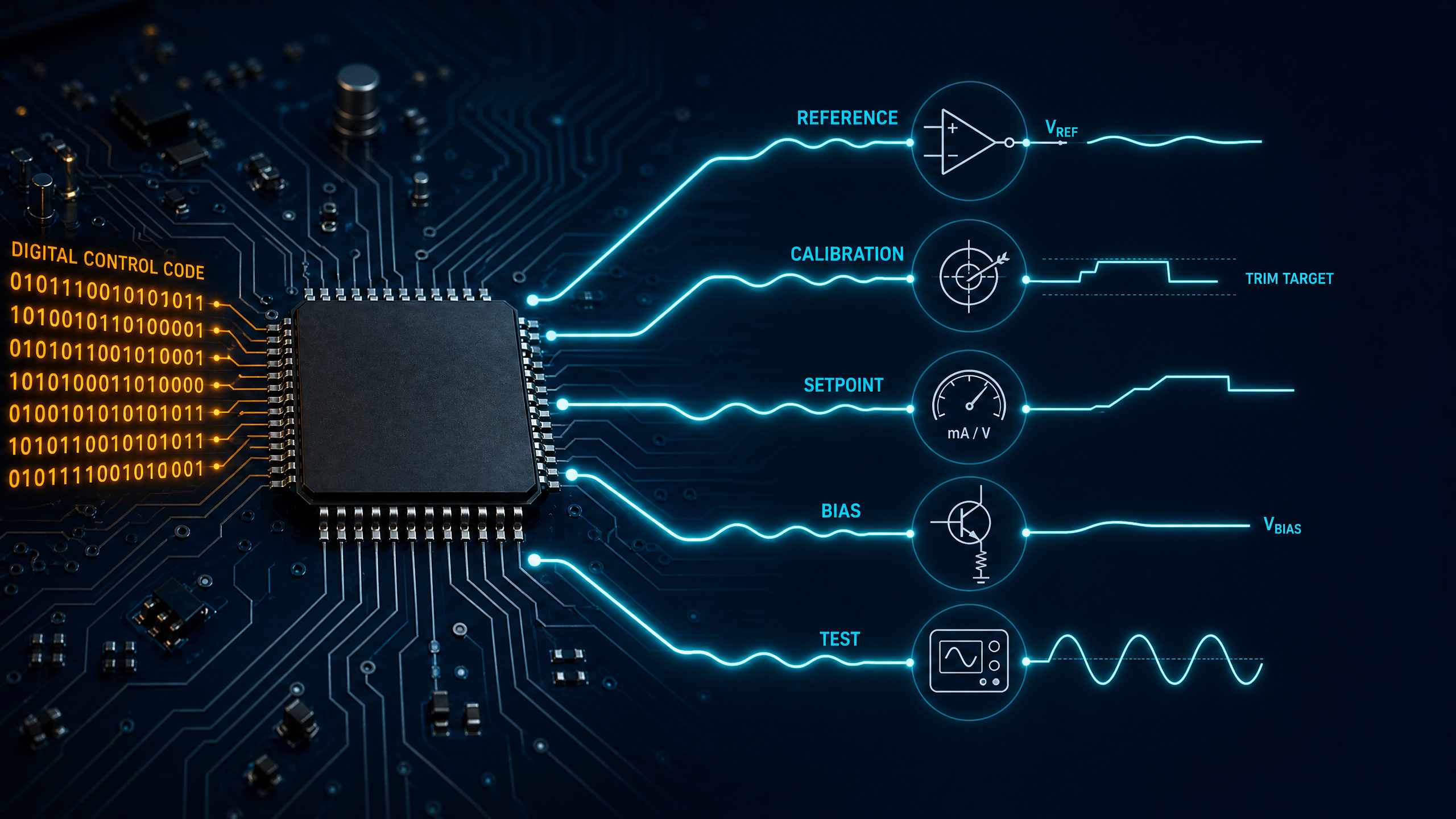
An external DAC IC is most useful when the analog signal is a design requirement, not just a convenience feature. Examples include programmable power-supply control, sensor calibration, closed-loop actuator control, analog test stimulus, bias generation, and factory-adjustable trim. In those cases, treating the DAC as a formal BOM item helps engineering and purchasing evaluate the same requirements: resolution, reference, interface, package, temperature range, and lifecycle.
Common mistake: choosing an external DAC only because the phrase DAC appears in the application note. Many systems can avoid a separate DAC chip if the controlled device already accepts I2C, SPI, UART, PWM, or a digital setpoint register. The stronger reason to add a DAC is when the receiving circuit actually measures or responds to an analog level.
When a Design Needs a Real Analog Output
Use an external digital to analog converter IC when the next circuit block cannot be driven cleanly by a digital signal. Typical cases include programmable references, calibration outputs, waveform generation, industrial setpoint control, and multi-channel control.
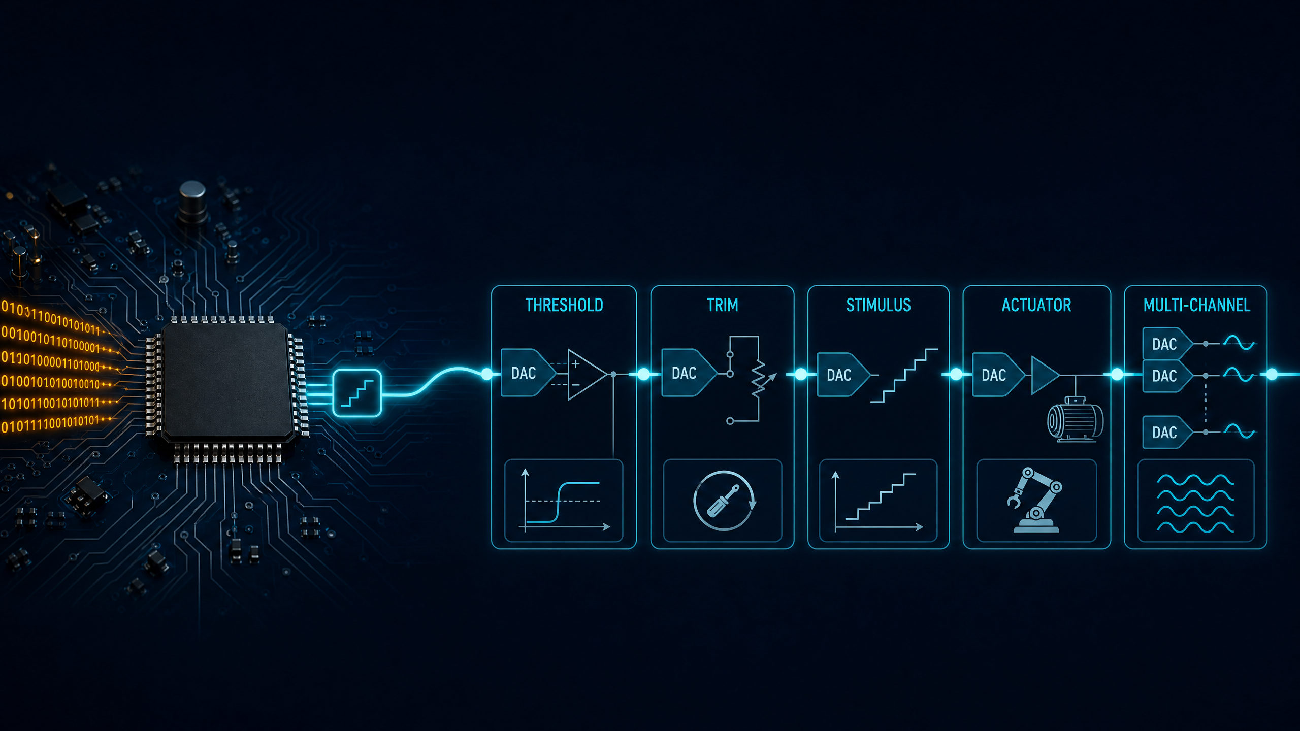
| Application | Why a real analog output matters | BOM implication |
|---|---|---|
| Programmable reference or threshold | The downstream comparator, ADC front end, regulator, or analog loop expects a voltage level | Specify resolution, output range, reference source, drift, and startup state |
| Calibration and trimming | The output replaces a potentiometer, resistor trim, or factory adjustment | Check nonvolatile memory, write endurance, and production programming flow |
| Waveform or stimulus generation | The system needs stepped or updated analog output values | Compare update rate, settling time, glitch energy, and output buffer needs |
| Industrial setpoint control | The actuator, PLC input, or control loop expects analog command behavior | Confirm voltage/current output type, isolation strategy, load, and protection |
| Multi-channel control | Several analog nodes must be controlled by firmware | Specify channel count, simultaneous update needs, crosstalk, and interface bandwidth |
The most important design point is that a DAC output is not only a number of bits. A 12-bit DAC with a poor reference, noisy layout, slow output buffer, or unsuitable load may perform worse than expected.
When PWM, a Built-In DAC, or a Digital Interface May Be Enough
You may not need a separate DAC chip when the analog output is slow, approximate, or already handled by another component.
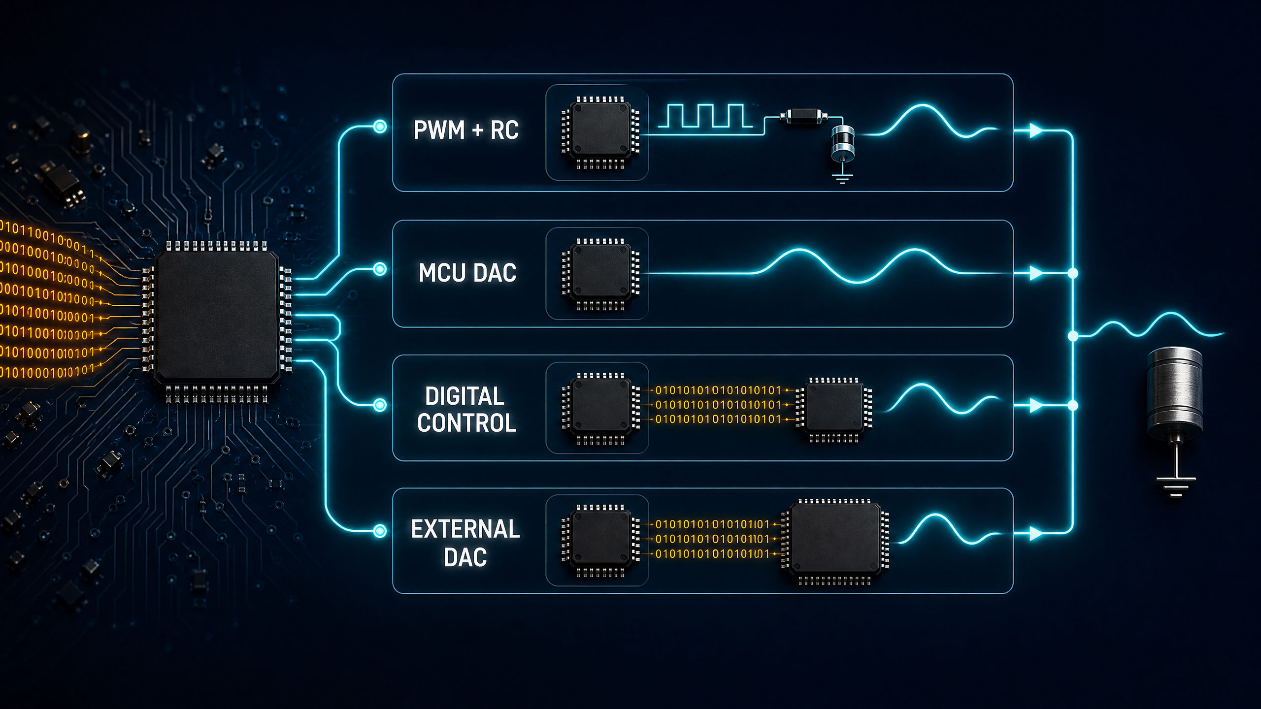
PWM plus an RC filter can be enough for simple brightness control, fan speed references, coarse bias levels, or noncritical setpoints. It is attractive because it uses a timer pin and passive components. The tradeoff is ripple, response time, load sensitivity, noise coupling, and the need to choose filter values carefully. PWM does not replace a precision DAC when monotonicity, low ripple, calibrated output, or fast settling is required.
A built-in microcontroller DAC can be enough when its resolution, output range, speed, and drive capability match the system. But built-in DAC blocks vary widely. Some have limited resolution, output drive, reference options, linearity, or channel count. If the built-in function becomes the limiting analog block, compare it with an external DAC IC using the decision criteria in this guide and check the digital-to-analog converter IC category for alternative parts.
A digital interface may also remove the need for a DAC. Digital potentiometers, digital power controllers, smart sensors, LED drivers, motor drivers, and programmable regulators may accept commands directly. If the receiving part can accept a digital command with the required precision and timing, keep the signal digital. If it needs a stable analog voltage or current, define the analog output requirement first and then choose the DAC architecture.
Accuracy, Noise, Settling Time, Channel Count, and Reference Design
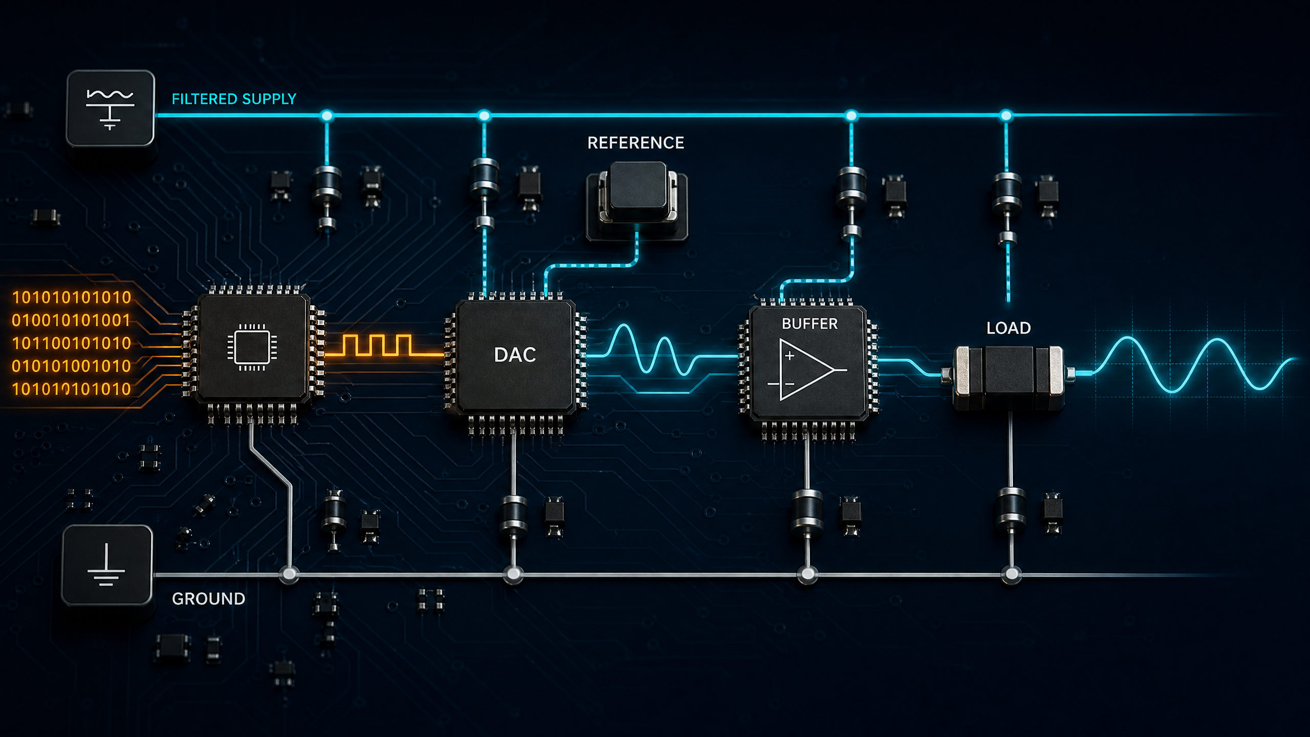
When an external DAC IC is justified, choose it from the signal-chain requirements instead of from the bit count alone. Resolution sets the code step size, but INL, DNL, offset, gain error, drift, settling time, reference quality, output drive, and layout determine whether the circuit performs as expected.
| Requirement | What to specify | Why it changes the DAC choice |
|---|---|---|
| Resolution | 8-bit, 10-bit, 12-bit, 16-bit, or higher | Sets the code step size, but not total accuracy by itself |
| Accuracy | INL, DNL, offset error, gain error, drift | Determines how close the output is to the ideal transfer curve |
| Output type | Voltage output, current output, buffered, unbuffered | Affects load drive, external amplifier needs, and output range |
| Settling time | Time to settle within a defined error band after a code change | Critical for waveform, control-loop, and test applications |
| Reference | Internal reference, external reference, reference input range | Often dominates gain accuracy and temperature behavior |
| Interface | I2C, SPI, parallel, or other logic interface | Affects firmware, update rate, pin count, and isolation options |
Reference design is a common failure point. A DAC output is usually proportional to a reference voltage or current. If the reference is noisy, drifting, overloaded, poorly bypassed, or shared with a noisy load, the output will carry that error. For precision applications, specify the reference source, layout approach, output buffer, and load range together. For a broader component selection checklist, review the DAC selection guide on the category page.
MCP4725, DAC0800/DAC0808, and Other DAC IC Examples
Specific DAC examples help show why the requirement matters. They are not automatic recommendations for every new design.
| Example DAC IC | What it illustrates | Design and sourcing notes |
|---|---|---|
| MCP4725 | A single-channel, 12-bit, buffered voltage-output DAC with I2C interface and nonvolatile memory according to Microchip documentation | Useful as a compact serial DAC example. Microchip’s current product page lists it as not recommended for new designs; lifecycle and ordering-code suitability must be rechecked before a new BOM. |
| DAC0800 | A monolithic 8-bit high-speed current-output DAC series according to TI product information | Useful as a current-output parallel DAC class. Do not assume it fits low-pin-count MCU designs without checking interface and output-stage needs. |
| DAC0808 | An 8-bit D/A converter with full-scale output current settling behavior specified in TI documentation | Use the exact orderable part number before quoting: confirm package, temperature range, lifecycle status, compliance documents, current stock, price, lead time, and whether the existing board can accept the device without schematic or firmware changes. |
How to Specify DAC Requirements in a BOM
A BOM line that only says DAC IC is not enough for sourcing. It forces the supplier to guess technical constraints and increases the chance of wrong substitutions. Instead, specify the requirement in a way that both engineering and procurement can validate.
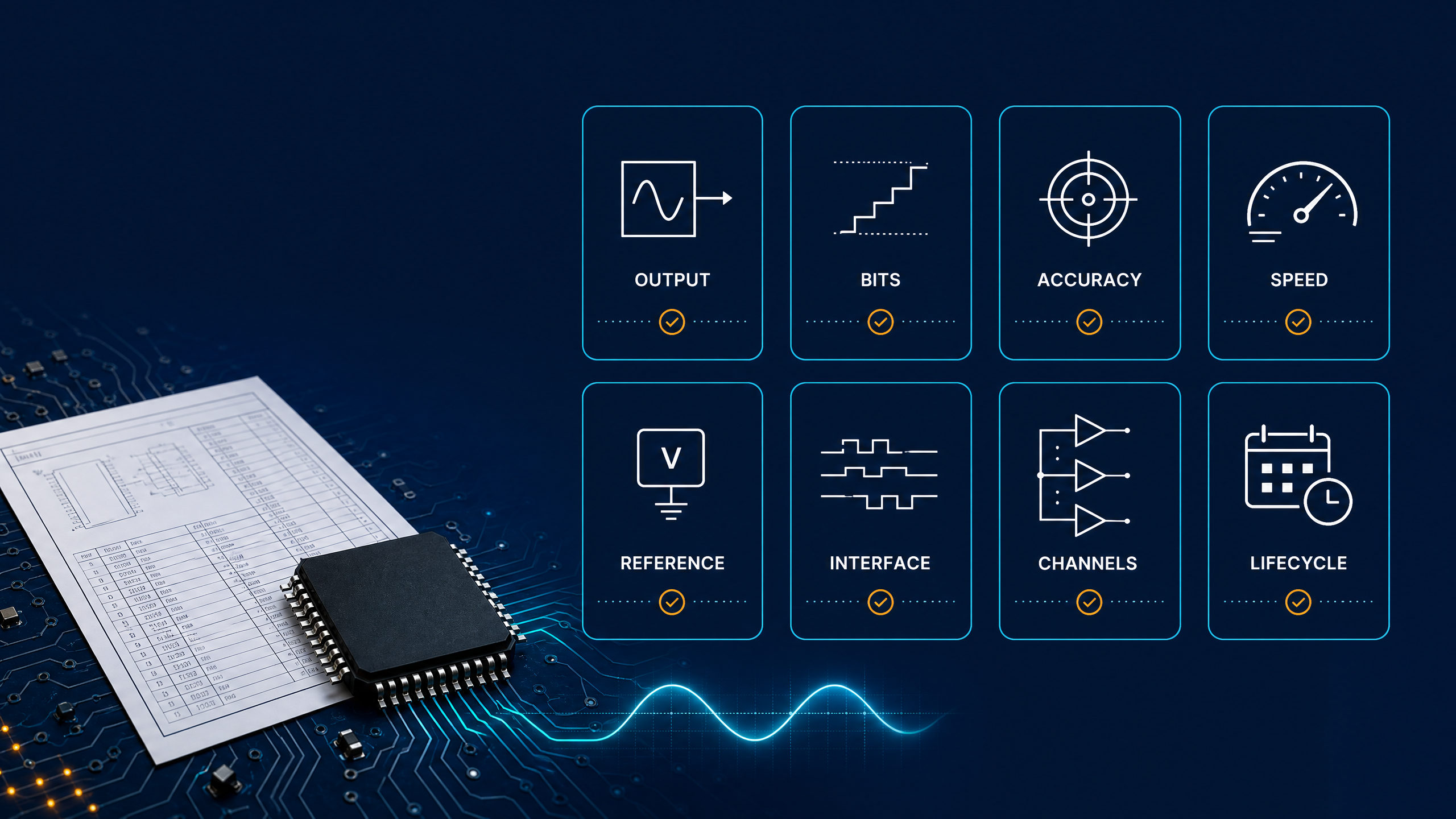
| BOM field | What to provide | If unknown |
|---|---|---|
| Function | Setpoint, trim, waveform, reference, calibration, industrial output, bias | Describe the circuit block being driven |
| Output type | Voltage or current output, buffered or unbuffered | State the load impedance and output range |
| Resolution | Required bits and minimum usable step size | Provide target analog step size |
| Accuracy | INL/DNL, offset, gain error, drift, or calibration method | Mark as engineering review required |
| Speed | Update rate and settling-time requirement | State slow control or fast waveform as a starting point |
| Reference | Internal reference, external reference, reference voltage/current | Identify whether the reference is already in the design |
| Interface | I2C, SPI, parallel, logic voltage, address needs | List MCU/FPGA logic voltage and available pins |
| Lifecycle and sourcing | Active/new-design preference, approved manufacturers, alternates | Check manufacturer lifecycle status first; then confirm stock, price, lead time, date code, compliance documents, and approved alternates during the current RFQ |
A clear BOM line could read:
DAC IC, 12-bit minimum, I2C or SPI, voltage output, 0 V to 3.3 V range,
single channel, suitable for MCU-controlled setpoint, package and
lifecycle to be confirmed before approval.
Avoid These BOM Mistakes
- Do not specify only the bit count. A 12-bit DAC with poor reference performance may not meet a 12-bit accuracy expectation.
- Do not treat current-output and voltage-output DACs as interchangeable. They require different output circuits.
- Do not assume an I2C DAC can replace a parallel DAC or an SPI DAC without firmware and timing review.
- Do not call a substitute compatible unless pinout, package, electrical limits, temperature, timing, output behavior, firmware, and compliance have been checked.
- Do not use marketplace stock screenshots as design evidence. Stock, price, lead time, and package availability must be verified during RFQ.
Related DAC Guides
FAQ
Do you really need a DAC IC?
You need a DAC IC when your system requires a controlled analog voltage or current that cannot be delivered accurately enough by PWM, a built-in DAC, or a digital interface. If the output is slow and noncritical, an MCU timer, built-in DAC, or digitally controlled load may be enough.
Is PWM the same as a DAC?
No. PWM is a digital pulse train whose average value can be filtered into an approximate analog level. A DAC IC directly converts digital code into an analog output and is usually easier to specify when ripple, accuracy, monotonicity, settling time, or calibration matters.
When should I use an external DAC instead of a microcontroller DAC?
Use an external DAC when the MCU’s built-in DAC does not meet resolution, accuracy, noise, output drive, reference, channel count, or lifecycle requirements. The decision should be based on the analog-output requirement, not only on whether the MCU datasheet lists a DAC peripheral.
Is MCP4725 a good DAC chip for every new design?
No. MCP4725 is a useful example of a 12-bit I2C voltage-output DAC with EEPROM, but Microchip’s current product page lists it as not recommended for new designs. For a production BOM, verify lifecycle, package, sourcing, and alternatives before approval.
Can DAC0800 or DAC0808 replace a modern serial DAC IC?
Not without review. DAC0800 and DAC0808 are 8-bit current-output DAC examples, while many modern MCU designs use serial voltage-output DACs. Interface, output circuit, timing, supply, package, firmware, and sourcing requirements must be checked before any replacement claim.
Need Help Specifying a DAC IC for Your BOM?
Send the part number, required resolution, output type, interface, reference voltage, package, quantity, and target application. We can help check availability and identify suitable alternative candidates subject to datasheet verification.
References and Further Reading
- Microchip — MCP4725 Product Information
- Microchip — MCP4725 12-Bit Digital-to-Analog Converter with EEPROM Memory Datasheet
- Texas Instruments — DAC0800/DAC0802 8-Bit Digital-to-Analog Converters Datasheet
- Texas Instruments — AN-1525 Single Supply Operation of the DAC0800 and DAC0802
- Texas Instruments — Digital-to-Analog Converters (DACs) Portfolio Overview
Technical note: DAC examples and equations in this guide are for explanation and initial screening. Production designs and BOM decisions should use the electrical characteristics, timing diagrams, transfer-function definitions, and lifecycle status in the exact part datasheet.