
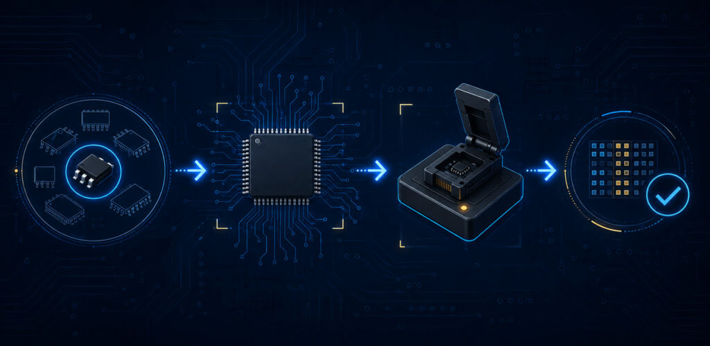
EEPROM programming is not simply sending bytes to a memory IC. A reliable design must match the device interface, address organization, page-write behavior, internal write-cycle handling, write protection, endurance limits and production-programming plan. For an OEM or EMS buyer, the practical question is whether the exact orderable EEPROM can be programmed, verified and maintained under the product’s real voltage, temperature, update-rate and manufacturing conditions.
For electrically updateable non-volatile storage after assembly, start with the EEPROM memory ICs resource hub. This guide focuses on programming readiness before an EEPROM enters a BOM.
EEPROM programming: the short answer
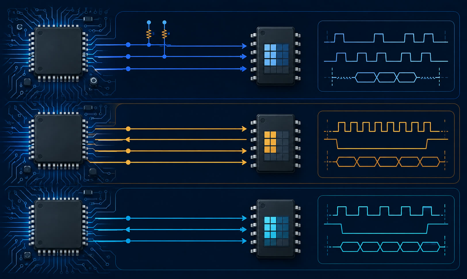
What EEPROM programming involves
| Layer | What to confirm | Why it matters |
|---|---|---|
| Device interface | I2C, SPI, Microwire or other supported protocol | MCU pins, firmware and fixture must match the device. |
| Memory organization | Density, addressing, page size and boundaries | Prevents rollover and incorrect addressing. |
| Write execution | Command sequence, write enable and completion detection | Avoids commands before the internal write finishes. |
| Data integrity | Power-loss behavior, CRC, protection and readback | Reduces the risk of incomplete production records. |
| Lifecycle control | Exact MPN, package, voltage, temperature and source rule | Prevents an unqualified variant entering the process. |
Choose the interface before writing firmware
Serial EEPROMs are commonly selected around the host interface. I2C can reduce pin count and support a shared bus; SPI can suit designs needing a separate chip select and direct serial transactions; Microwire has another command model. The correct choice follows MCU resources, bus topology, speed, firmware architecture, package and lifecycle constraints.
Read the I2C EEPROM vs SPI EEPROM guide, then verify voltage thresholds, timing, address format and maximum clock frequency in the exact device datasheet.
Respect page-write boundaries
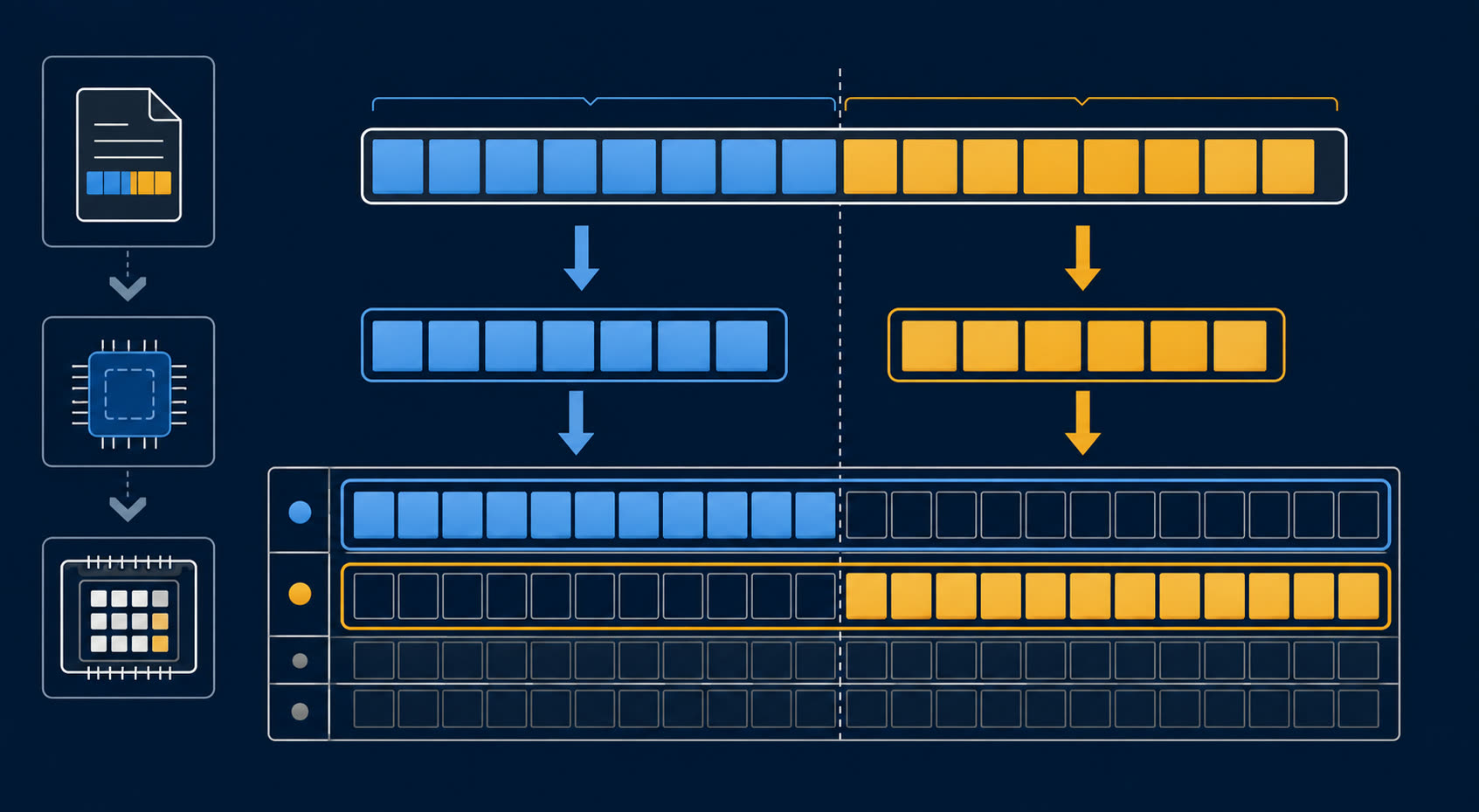
Many serial EEPROMs accept multiple bytes in a page write, then complete an internal erase/program operation. Page size is device-specific. A host that crosses the end of a page without handling the boundary can cause the address counter to roll over within that page and alter earlier data.
Microchip’s AT25M02 documentation warns that page rollover should be avoided because previously loaded data can be unintentionally altered. Split records at datasheet-defined boundaries rather than assuming one large write is safe. AT25M02 datasheet
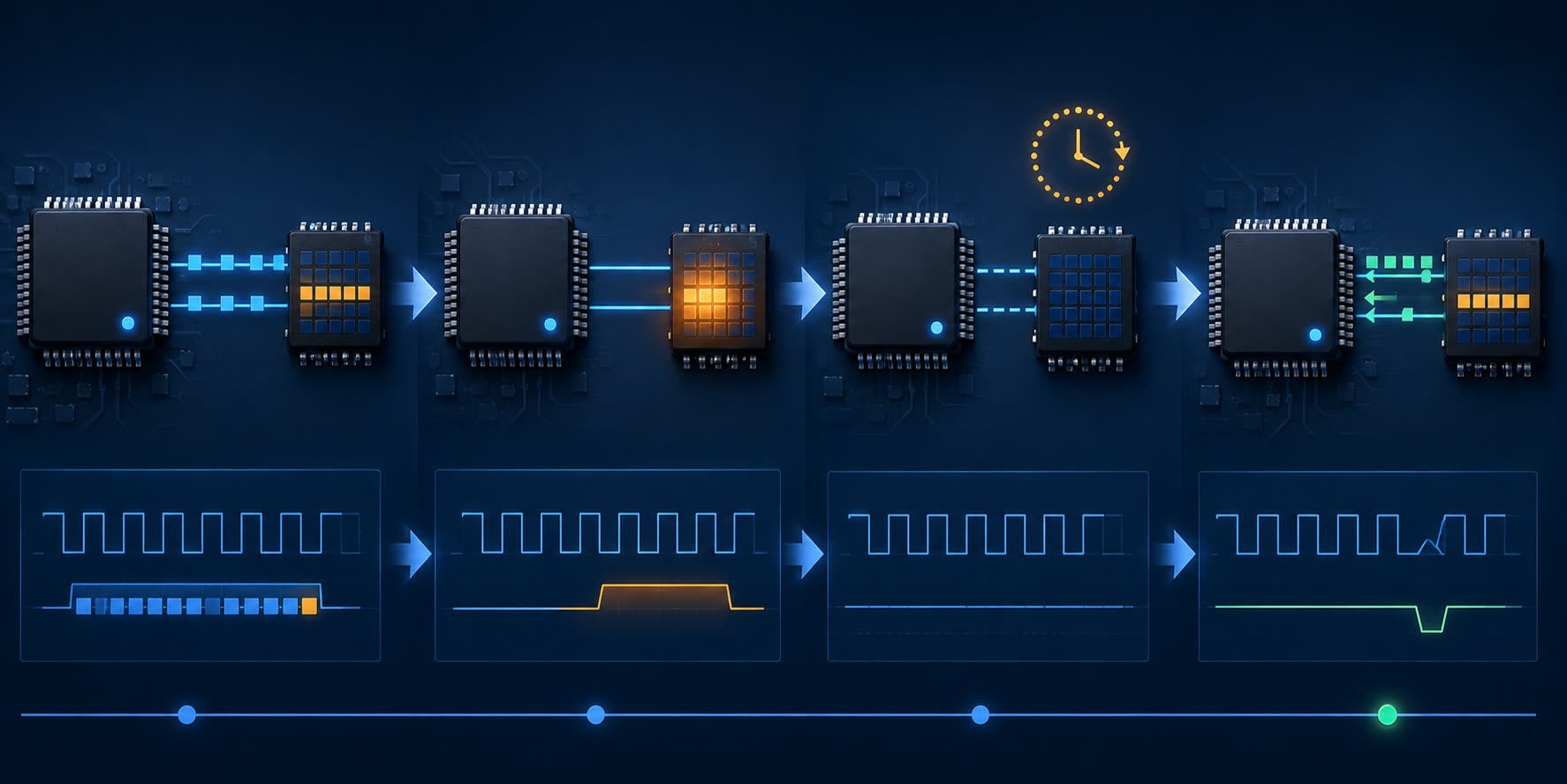
- Read the page size and address organization for the exact device.
- Divide records at page boundaries.
- Send only the allowed byte count for that operation.
- Detect or wait for completion before a dependent command.
- Read back critical programmed data during production validation.
Handle the internal write cycle correctly
EEPROM writes take longer than serial reads because the device completes an internal self-timed operation. The maximum time, status behavior and permitted polling method are device-specific.
Microchip’s AT24C08D documentation describes acknowledge polling, which allows the host to determine when the internal write has completed. Use such a method only as the exact part’s datasheet permits; do not assume a generic fixed delay proves completion. AT24C08D datasheet
Plan for power loss, data integrity and endurance
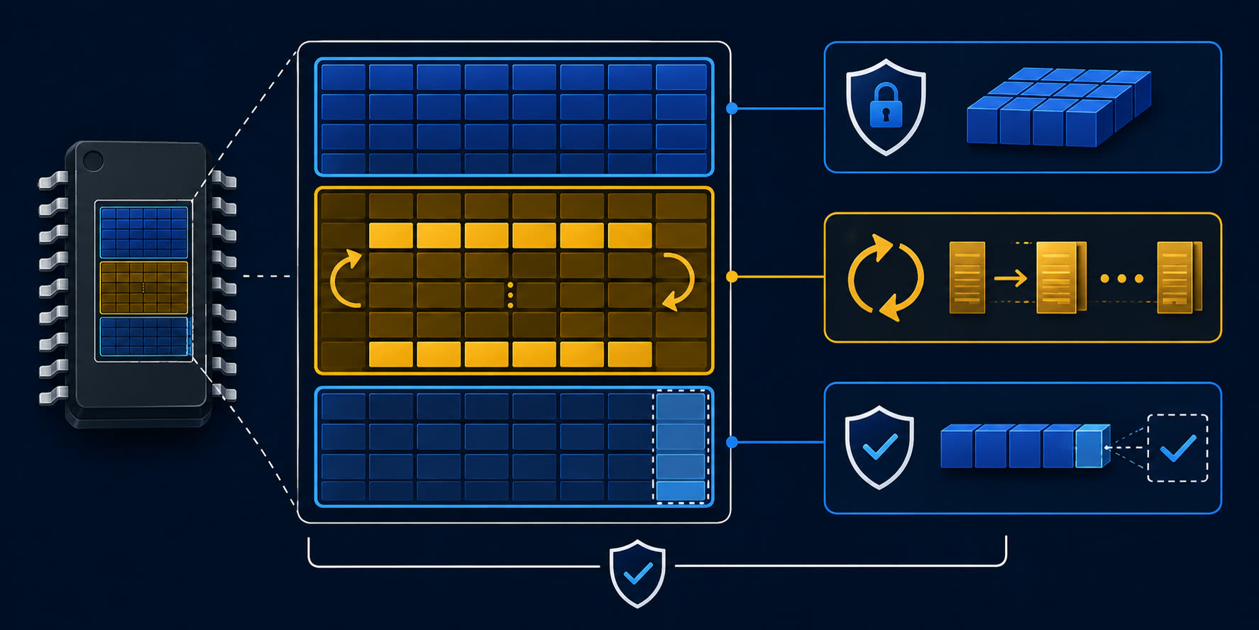
An interrupted write can leave an incomplete record or corrupt the addressed region. For field-updated data, consider a record structure with version, length, CRC or checksum, validity marker and a recoverable prior record where the application risk justifies it. Keep frequently updated data separate from factory configuration or read-only identifiers.
ST’s page-EEPROM guidance warns that a power-down during a page write can corrupt the entire addressed page and recommends separating read-only parameters from cycled data. Endurance is also device- and condition-specific: calculate writes per physical unit, temperature and product life before approval. ST AN5866
Production programming and BOM checks
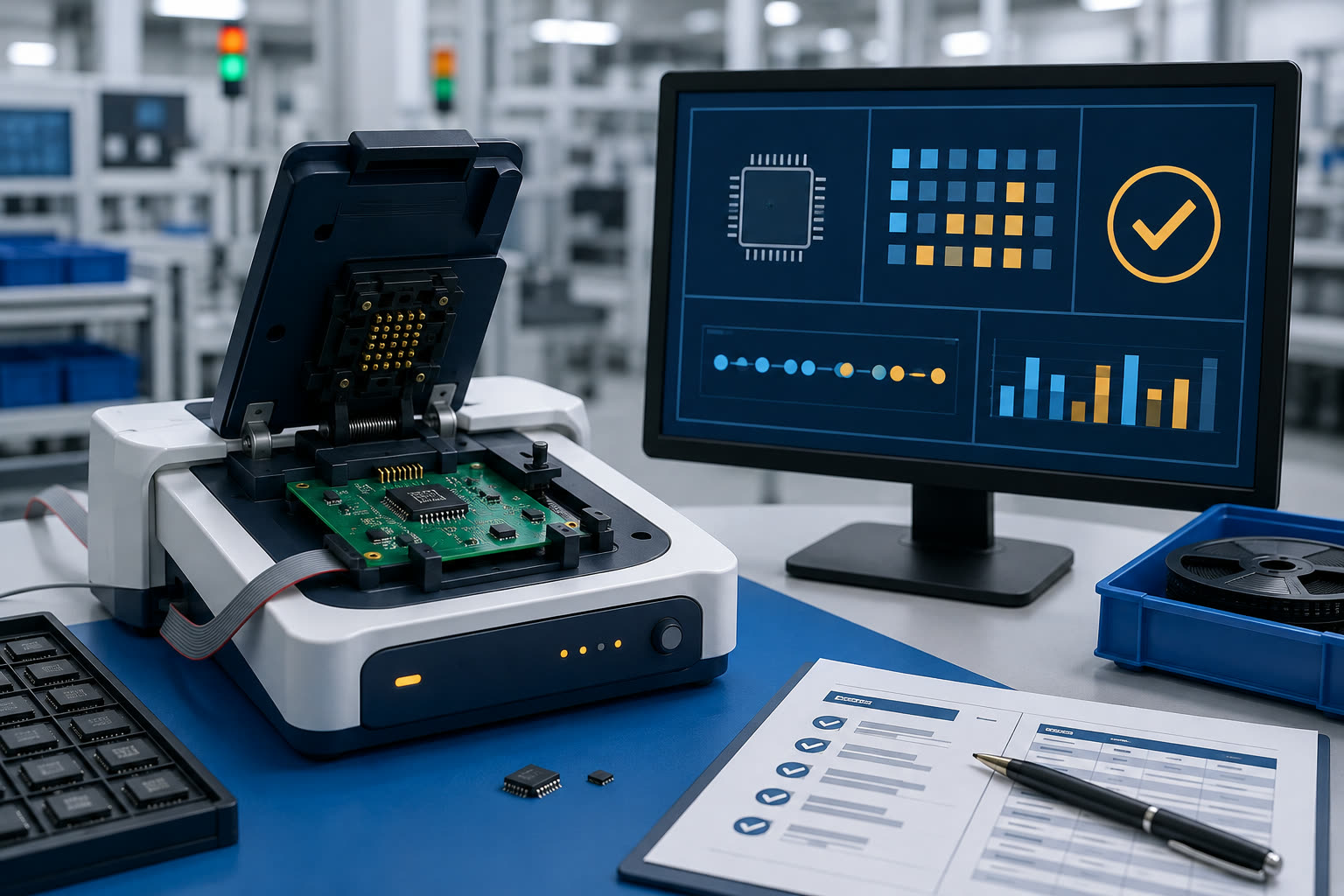
| Release item | Why it belongs in the programming package |
|---|---|
| Full manufacturer part number and suffix | Package, voltage, temperature, organization and features can differ. |
| Datasheet and device revision | Keeps driver and fixture configuration traceable. |
| Data map and byte order | Makes programmed fields and reserved regions explicit. |
| Page/write-cycle procedure | Prevents rollover, premature readback and protection errors. |
| Verify/readback criteria | Defines pass/fail behavior and test-record retention. |
| Change-control rule | Triggers review when the MPN, fixture, data format or firmware changes. |
Common production mistakes
- Releasing a base part number instead of the full approved orderable MPN.
- Writing a record across a page boundary.
- Verifying only the first bytes of a programmed region.
- Assuming a substitute is programming-compatible from capacity alone.
- Mixing frequently cycled data with factory-locked data.
EEPROM programming RFQ checklist
Need an EEPROM sourcing or programming-readiness review?
Send the manufacturer part number, package, quantity, voltage and temperature range, interface, density, update pattern, page/write-protection requirements, target delivery date and approved-alternative rules through the ApexComponent inquiry form. Current stock, price, lead time, compliance documentation, lifecycle status and alternative suitability require quote-time or manufacturer verification.
Frequently asked questions
How do you program an EEPROM?
Use the exact device’s supported interface and command sequence, split data at the correct page boundaries, then wait or poll for the internal write cycle according to its datasheet. Verify critical data as part of the production plan.
Can one EEPROM routine work with every serial EEPROM?
No. Interface, address format, opcodes, write-enable behavior, page size, timing and protection features differ between families. Validate the firmware for the exact orderable device.
Why does EEPROM page size matter?
It determines how many bytes an operation can accept and where firmware must split a record. Ignoring boundaries can risk rollover or unintended data changes.
Does EEPROM endurance guarantee product lifetime?
No. Endurance is conditional and device-specific. Estimate writes per physical unit, temperature and product life, then validate the exact design and update pattern.