
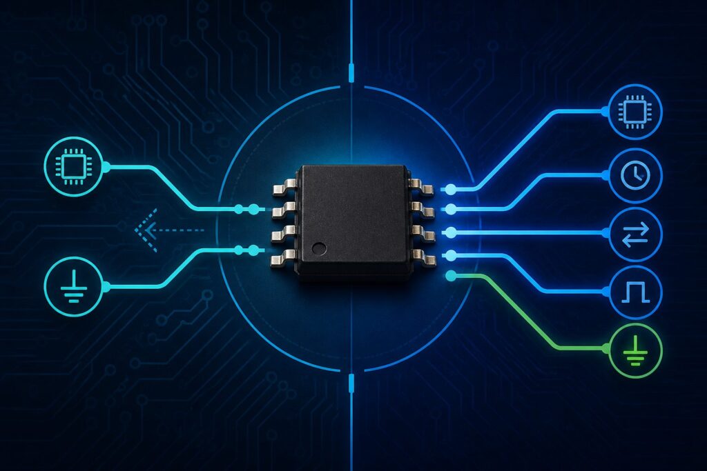
An I2C EEPROM is usually the better choice when a design must minimize MCU pin use, share one bus among several peripherals, or keep the control interface simple. An SPI EEPROM is usually better when faster transfers, predictable timing, or a dedicated point-to-point memory link matters more than pin count. Neither interface is automatically best: the correct EEPROM chip must also match density, supply voltage, temperature, package, write behavior, endurance, lifecycle, and sourcing requirements.
This guide is for embedded engineers, OEM/EMS buyers, and component sourcing teams comparing serial EEPROM options. For a broader definition of EEPROM technology and product families, start with the ApexComponent EEPROM resource hub. This article focuses on the narrower decision between I2C and SPI so the blog supports rather than duplicates the category page.
Last updated: August 31, 2026. Technical values below are portfolio examples, not universal limits. Confirm every value in the datasheet for the exact orderable part number.
I2C vs SPI EEPROM: quick comparison
| Selection factor | I2C EEPROM | SPI EEPROM |
|---|---|---|
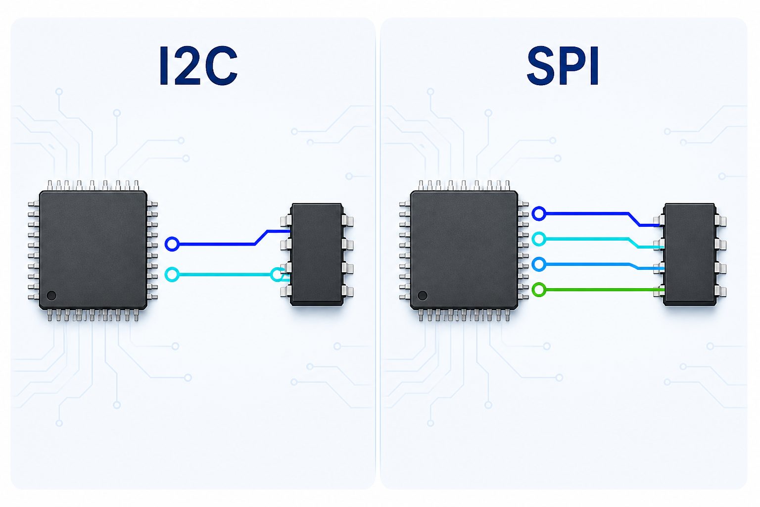
| Typical signals | SCL and SDA, plus power and optional address/write-protect pins | SCLK, MOSI, MISO and chip select, plus power and optional hold/write-protect pins |
| MCU pin use | Low; multiple addressed devices can share two bus signals | Higher; each additional device commonly needs another chip-select signal |
| Transfer behavior | Addressed, shared bus with pull-up and bus-capacitance considerations | Dedicated chip select and full-duplex shift interface with direct timing control |
| Speed positioning | Usually chosen for moderate-speed control and low pin count; high-speed I2C variants also exist | Usually chosen when higher serial clock rates and deterministic access matter |
| Scaling peripherals | Efficient when addresses and bus loading are managed correctly | Simple per-device control, but chip-select routing grows with device count |
| Good fit | Configuration, calibration, identification and modest event logging | Faster parameter transfer, denser logging and timing-sensitive control |
| Procurement check | Address options, pull-ups, clock support, page size and package | SPI mode, maximum clock at operating voltage, chip-select behavior and package |
What is an EEPROM chip?
An EEPROM chip is non-volatile memory that can retain stored information when power is removed and can be electrically rewritten in the system. Serial EEPROMs are commonly used for configuration parameters, calibration values, identification data, usage records and event logs—small but important data that must survive a power cycle.
EEPROM is a technology family, while I2C and SPI describe how the host communicates with a serial EEPROM. The interface does not by itself define the capacity, endurance, retention, write-cycle time, package, temperature rating or protection features. Those properties belong to the exact device and ordering suffix.
Microchip’s current serial EEPROM portfolio page illustrates the range available within one manufacturer: five serial bus types, densities from 128 bits to 4 Mbits, operating voltages from 1.5 V to 5.5 V, and temperature options from -40°C to 150°C. These are portfolio boundaries, not a promise that every part supports every value. The example shows why procurement must filter by exact part number instead of buying against the word “EEPROM” alone.
When should you choose an I2C EEPROM?
Choose an I2C EEPROM when two shared bus lines are more valuable than maximum transfer speed. I2C uses a clock line and a bidirectional data line. Devices are selected by address, allowing EEPROMs, sensors, GPIO expanders and other peripherals to share the same bus when electrical loading and address conflicts are controlled.
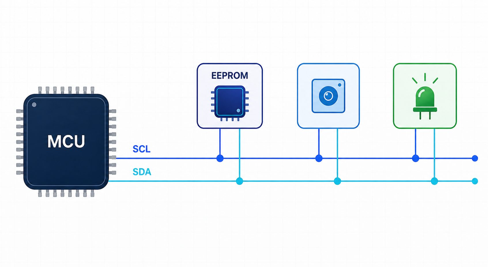
I2C is a strong fit for boards where the EEPROM stores startup configuration, calibration constants, device identity or a modest log. It is also useful when MCU pins are limited or when the host already exposes an I2C peripheral. ST describes its standard I2C EEPROM portfolio as a low-power, two-wire option that can share an external bus with sensors and other digital cores.
The design still needs engineering checks. Confirm the allowed device addresses, pull-up resistor values, total bus capacitance, maximum supported clock, page-write size, write-cycle time, voltage range, power-on behavior and write-protect implementation. A part can be electrically valid yet still fail the design if its address conflicts with another component or its package is not approved for the PCB.
Do not assume I2C always means 100 kHz or 400 kHz. Standard families often support up to 1 MHz, while specialized high-speed devices can go further. Microchip’s 24CS family, for example, introduced 3.4 MHz High-Speed mode. Treat that as a device-family capability, not a default for all 24-series EEPROMs.
When should you choose an SPI EEPROM?
Choose an SPI EEPROM when transfer speed, predictable timing or a dedicated memory connection matters more than conserving MCU pins. A conventional SPI link uses clock, controller-to-memory data, memory-to-controller data and chip select. The host directly selects the memory, which simplifies transaction ownership but requires more routing than a two-wire I2C bus.
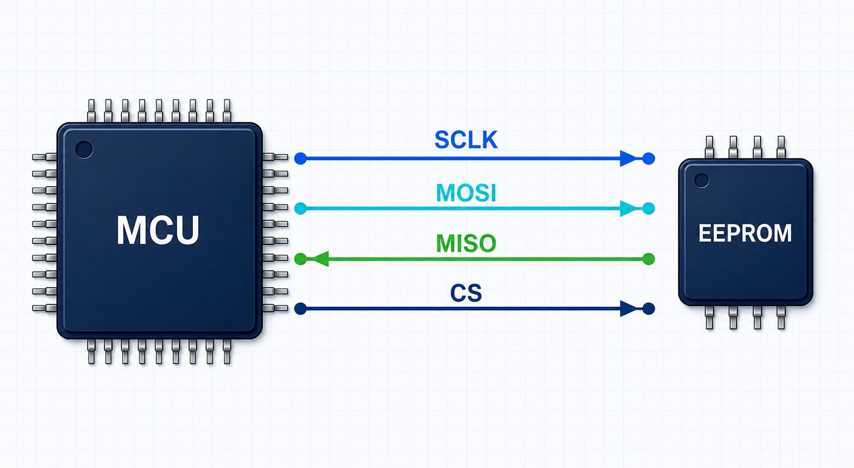
SPI EEPROM is attractive for faster parameter transfers, denser event logging, production programming and systems where shared-bus latency is undesirable. ST’s current standard EEPROM selection guide lists many M95 industrial devices at serial clock limits up to 20 MHz, with some densities specified at lower limits. Microchip likewise notes that SPI serial EEPROMs are commonly specified up to 20 MHz. The maximum clock depends on the exact device, supply voltage and datasheet conditions.
The main system tradeoff is scaling. Each memory commonly needs its own chip-select path, so adding devices consumes pins or requires extra logic. The engineer must also confirm SPI mode, clock polarity and phase, command set, status-register behavior, write enable/disable sequence, page boundaries and protection bits. “SPI-compatible” is not enough information for firmware release.
How to choose the right EEPROM interface
Choose the interface first from the host and timing constraints, then qualify the actual memory device. This order prevents a common sourcing mistake: selecting an attractive EEPROM part number before confirming that the MCU pins, bus, firmware and PCB can support it.
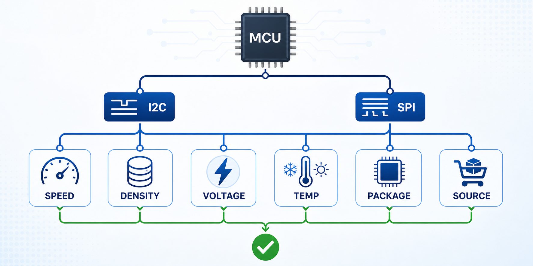
- Check the host interface. Confirm whether the MCU or FPGA has a free I2C or SPI peripheral and whether those pins are available in the selected package.
- Set the timing requirement. Estimate the largest transfer, required update interval and acceptable blocking time. Include write-cycle latency, not only serial clock rate.
- Calculate usable density. Include addressing overhead, metadata, wear management and expected future growth. Do not confuse Kbit with KB.
- Match electrical limits. Verify minimum and maximum supply voltage, logic compatibility, standby/active current and power-on behavior.
- Match the environment. Select the required operating temperature, qualification level and data-integrity features from documented sources.
- Confirm package and assembly. Check footprint, pinout, height, pitch, moisture sensitivity and assembly process. ST’s portfolio, for example, includes SO8N, TSSOP8, DFN, WLCSP and bare-die options, but availability differs by device.
- Verify protection and reliability. Review hardware/software write protection, lockable pages, endurance and retention at the application’s actual temperature and write pattern.
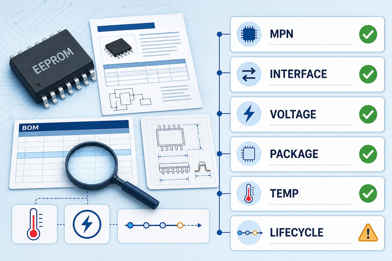
- Review lifecycle and sourcing. Use the full manufacturer part number. Confirm lifecycle, authorized channels, required compliance documents, quantity and delivery date during RFQ.
I2C EEPROM and SPI EEPROM product examples
Part numbers should be grouped by interface, then validated against the manufacturer datasheet. Current ApexComponent catalog examples include 24LC512T-I/SN and M24C64-FMC6TG for I2C designs, plus M95512-DFMC6TG and AT25M02-SSHD-T for SPI designs.
Common EEPROM sourcing mistakes
- Confusing Kbit with KB: a 512-Kbit EEPROM stores 64 KB, not 512 KB.
- Buying by base number only: suffixes can change package, temperature grade, packing and other orderable details.
- Assuming every I2C or SPI part is firmware-compatible: addresses, commands, page sizes and protection behavior can differ.
- Ignoring voltage-dependent speed: the headline clock may apply only at a specified supply voltage.
- Treating endurance as one universal number: endurance depends on device family, temperature, write pattern and test conditions.
- Publishing static supply promises: stock, price, lead time and compliance status change and must be confirmed for the exact suffix, quantity and quote date.
Frequently asked questions
Is I2C EEPROM slower than SPI EEPROM?
Usually, standard I2C EEPROM operates at a lower serial clock than standard SPI EEPROM, but the exact limits depend on the device. ST’s current standard selection guide shows many I2C devices at up to 1 MHz and many SPI devices at up to 20 MHz. High-Speed I2C EEPROM families also exist, so compare exact datasheets rather than relying only on interface names.
Can I replace an I2C EEPROM with an SPI EEPROM?
Not as a drop-in substitution. I2C and SPI use different signals, protocols and firmware drivers. Changing interfaces normally requires schematic, PCB and software changes. Even within one interface, verify pinout, density, addressing, page size, write protection, voltage, timing and package before approving an alternative.
Which EEPROM interface uses fewer MCU pins?
I2C generally uses fewer MCU pins because SCL and SDA can be shared across multiple addressed devices. Conventional SPI typically uses clock, two data signals and at least one chip-select signal. Additional SPI memories commonly need additional chip-select paths.
What information should an EEPROM RFQ include?
Include the complete manufacturer part number, manufacturer preference, interface, density, package, voltage, temperature grade, qualification or compliance requirements, quantity, target delivery date, date-code restrictions and approved-alternative rules. If a substitute is allowed, specify whether firmware or PCB changes are acceptable.
Should I choose EEPROM by clock speed alone?
No. Clock speed is only one interface parameter. The actual design must also account for write-cycle time, page size, density, endurance, retention, voltage, package, temperature, protection features, lifecycle and sourcing. A faster part is not useful if it fails another required condition.
EEPROM sourcing and BOM review
Need help comparing I2C EEPROM and SPI EEPROM part numbers?
Send the complete manufacturer part numbers, package, quantity, voltage, operating temperature, application, target delivery date and approved-alternative rules through the ApexComponent inquiry form. Current stock, price, lead time, compliance documents and replacement suitability will require quote-time verification.