

Most intermittent RS-485 failures are physical-layer problems before they are Modbus or firmware problems. When communication works on a bench but fails after a motor, heater, VFD, or injection machine starts, begin with the cable, waveform, driver-enable timing, idle-state voltage, and common-mode voltage.
RS-485 remains common in industrial equipment because a differential pair can support a shared multipoint bus over practical field cabling. It is an electrical interface, not a complete protocol. The same pair can carry Modbus RTU, a proprietary UART protocol, or another higher-level protocol, so a clean-looking packet log cannot prove that the physical layer is healthy.
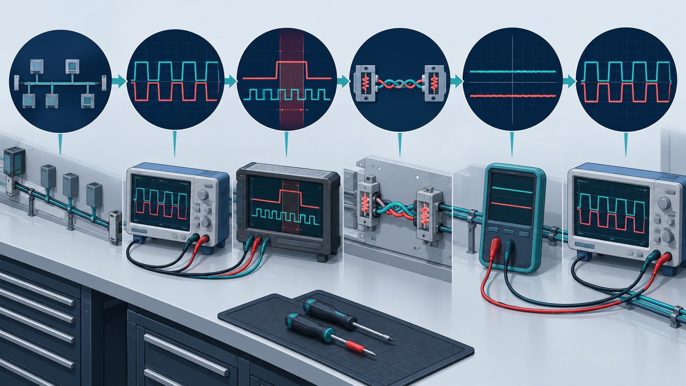
The seven-step field sequence
- Map the installed topology. Identify the two physical cable ends, every branch or stub, the nominated termination points, and which node is allowed to drive the pair at each instant.
- Measure the differential signal. Inspect A-B with an appropriate differential probe or safe measurement method. A and B measured individually to local ground do not show the receiver's differential input by themselves.
- Check transmitter ownership. Capture UART TX, DE, and the bus together. Confirm that one node drives the pair at a time and that the last stop bit has left the line before DE is released.
- Verify termination at the physical ends. Compare the installed termination strategy with cable impedance, edge rate, baud rate, and actual topology.
- Verify the idle state. With no active transmitter, check that the bus has a defined differential state or that every receiver is specified to provide a suitable true fail-safe response.
- Measure common mode and ground potential. Compare the bus voltage relative to each endpoint's local signal reference, especially while nearby equipment switches.
- Simplify, then rebuild. Test two known-good nodes on a direct cable, reduce baud rate as a diagnostic experiment, then add nodes and cable sections one at a time.
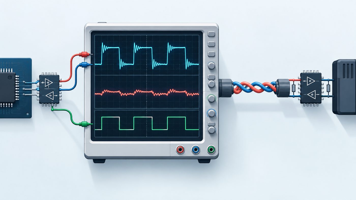
DE timing: a valid byte can still be cut off
In a two-wire half-duplex RS-485 design, the driver must be disconnected when the node is not transmitting. On a typical transceiver, a logic high at DE enables the driver and a logic low places it in a high-impedance state. That behavior permits a second node to use the shared pair. ADI AN-960 describes this driver-enable role and the half-duplex bus arrangement.
The common implementation failure is releasing DE when a DMA transfer has finished or when the UART transmit FIFO is empty. Those events may occur before the final stop bit has shifted onto the wire. Use the UART's transmission-complete indication, then apply any device-specific enable/disable timing from the transceiver data sheet. Do not reuse an arbitrary delay from another board.
This is separate from Modbus RTU frame timing. The Modbus serial-line specification defines an inter-frame silent interval of at least 3.5 character times; it does not replace the need to let the local UART physically finish the outgoing byte. See the Modbus Serial Line Protocol and Implementation Guide for the protocol timing definition.
Termination is a transmission-line decision, not a default footprint value
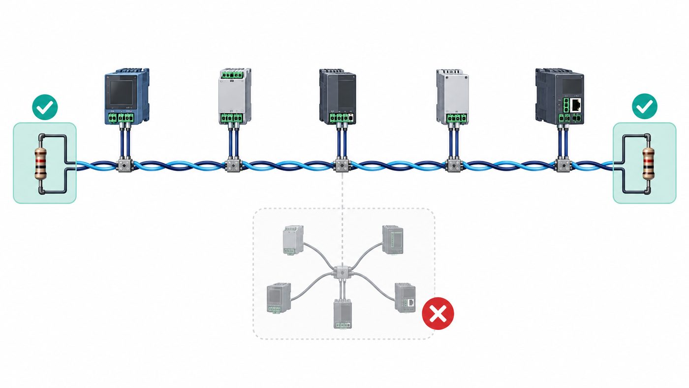
An RS-485 termination resistor is normally placed across A and B at the two electrical ends of a transmission line and is selected to approximate the cable's characteristic impedance. Two 120 ohm terminators are common on nominal 120 ohm cable, but 120 ohm is not a universal rule and not every short, slow-edge-rate link needs parallel termination.
The right question is whether line delay is meaningful compared with the driver's transition time and whether reflected edges can cross the receiver threshold. ADI notes that reflections occur around signal transitions and are more likely to cause misreads as line delay becomes significant; it also states that a parallel-terminated RS-485 network should have no more than two terminators, independent of node count. Read the termination guidance.
- With power removed, measure A-to-B resistance only as a quick topology clue. About 60 ohm is consistent with two 120 ohm terminators in parallel, but bias networks and connected circuitry can alter the reading.
- Do not put a terminator at every node. Excess parallel termination loads the driver and reduces differential margin.
- Keep stubs short and avoid star wiring unless the system was deliberately designed and validated for it.
- When the waveform rings, record cable length, baud rate, transceiver slew rate, probe method, and terminator locations before changing values.
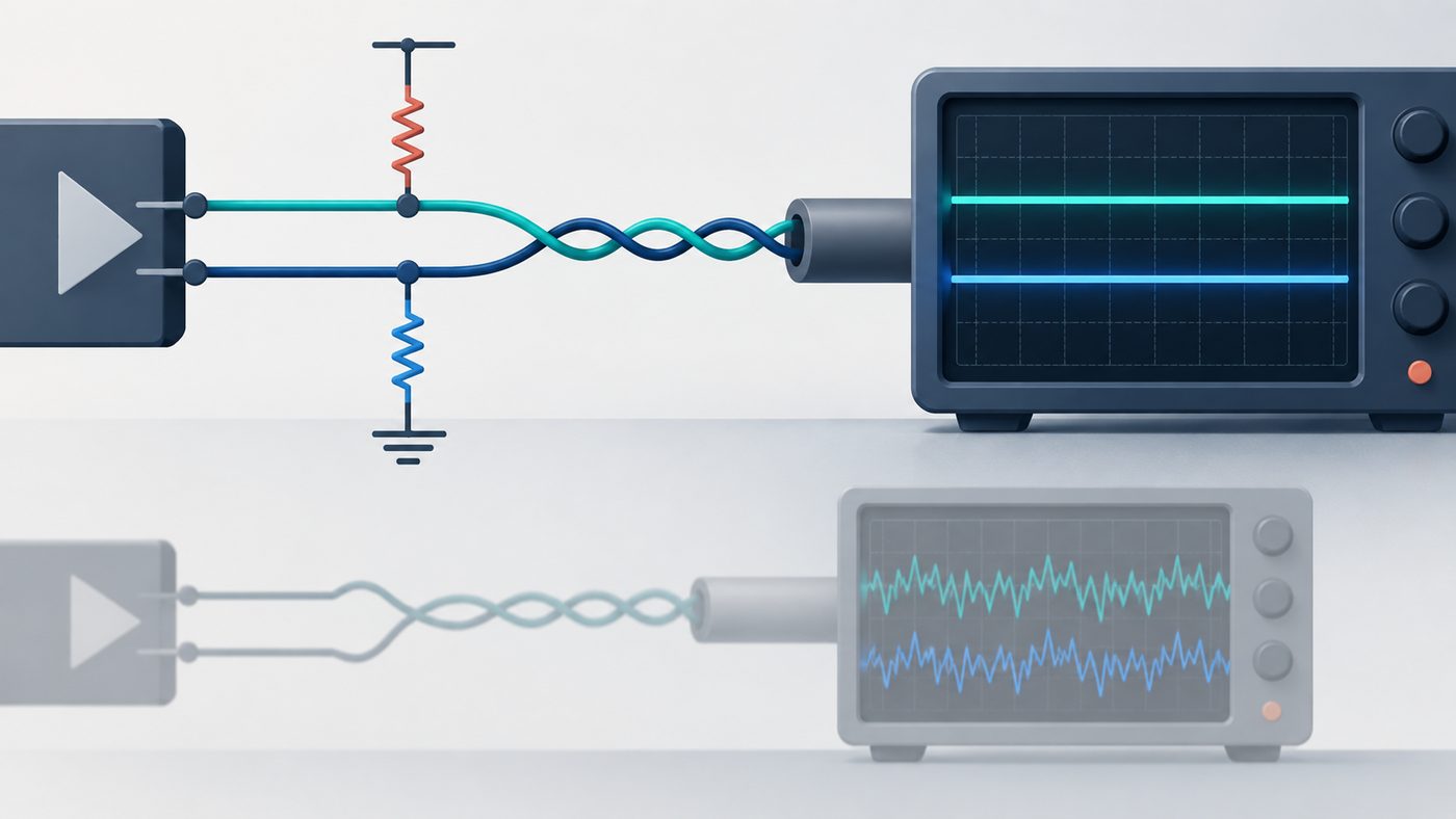
Biasing: define the idle bus before the UART invents a start bit
When every driver is disabled, an older or non-fail-safe receiver can see an undefined differential input. The UART may then interpret noise as false start bits, framing errors, or random characters. A pull-up/pull-down bias network at one controlled location can establish an idle differential state. ADI shows why a floating bus can produce random data and why the bias network must create adequate differential margin. See the fail-safe-biasing section.
Do not copy resistor values without calculating the loaded circuit. Parallel termination, supply voltage, receiver input loading, cable leakage, and the required differential threshold all affect the result. For a simple symmetric network with one pull-up, one pull-down, and an equivalent A-B termination resistance, a first-order estimate is:
That is a starting calculation, not a release criterion. Confirm the receiver's guaranteed threshold and fail-safe behavior in the exact data sheet, then verify the idle differential voltage at the field bus. A transceiver marketed with true fail-safe inputs may reduce or remove the need for external biasing in a specific design, but that feature is device-specific.
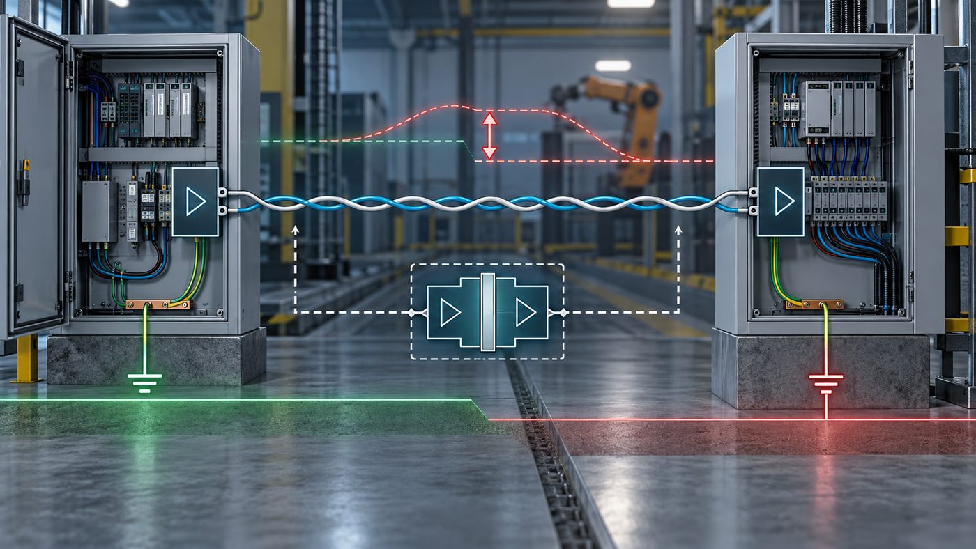
Differential signaling is not permission to ignore ground potential
RS-485 receivers reject common noise only inside their allowed common-mode range. In the standard RS-485 range described by ADI, the receiver must tolerate -7 V to +12 V common-mode voltage while disconnected from the bus. The relevant measurement is not simply A-to-ground or B-to-ground at one node. It is the relationship between the bus and the local reference at each endpoint, particularly during the event that causes errors. ADI's circuit guide defines the common-mode range and explains why long links can see ground-potential differences.
If endpoints are in different buildings, on different power systems, or exposed to high-energy switching, evaluate galvanic isolation and an isolated power strategy. Isolation can break ground-current paths, but it must be designed as a system: signal isolation alone is not automatically enough. The same review should cover transient protection, cable routing, enclosure bonding, and the site's EMC and safety constraints.
When a motor starts, use time correlation as evidence
If errors begin at the moment a VFD, contactor, heater bank, or injection machine switches, treat the timing as useful evidence. Capture the switching event, A-B differential voltage, common-mode voltage, DE, and UART TX/RX in the same time window. A packet checksum failure tells you that data changed; the waveform capture can show whether the cause was reflection, contention, a common-mode excursion, or a supply/reference disturbance.
Be cautious with scope grounding. An earth-referenced probe ground clip can create a fault if it is attached to a floating point. Use a suitable differential probe or an approved isolated measurement setup for the equipment under test.
A controlled repair checklist
| Check | Evidence to retain |
|---|---|
| Topology | Cable sketch, node count, endpoint locations, and any stubs |
| Termination | Resistance values, exact locations, and powered-off A-B measurement |
| Bias/fail-safe | Transceiver data-sheet reference and measured idle differential voltage |
| DE timing | Capture showing UART completion, DE, and the final bus transition |
| Common mode | Measurements at both endpoints during normal operation and the fault event |
| Protection | TVS/isolation part numbers and grounding or shield-bonding arrangement |
| Retest | Direct two-node test, restored topology, baud-rate test, and fault-event result |
Reducing baud rate can be a useful experiment. If errors disappear only at lower speed, the result points toward signal integrity, timing margin, topology, or noise coupling; it does not prove that firmware is correct. Restore the intended operating condition after the physical cause has been identified.
What to send for a design or BOM review
For an RS-485 repair or transceiver replacement review, send the exact manufacturer part number, schematic excerpt, controller voltage, cable type and length, bus topology, terminator and bias values, isolation/protection parts, intended baud rate, and a scope capture captured at the fault. An interface-family label alone is not enough to approve a substitute.
FAQ
Do I always need a 120 ohm resistor on RS-485?
No. Use termination when the installed cable behaves as a transmission line at the driver's edge rate, then match the cable's characteristic impedance at the physical ends. Two 120 ohm resistors are common with nominal 120 ohm cable, but the correct value and need depend on the cable, topology, edge rate, and baud rate.
Why does RS-485 work on the bench but fail when a motor starts?
The switching event can couple noise into the cable, create a ground-potential shift, disturb a supply reference, or expose marginal termination or biasing. Correlate the event with a capture of A-B, common mode, DE, and UART signals before changing protocol settings.
Can a multimeter prove that RS-485 biasing is correct?
No. A multimeter can be useful for a static check, but it usually cannot reveal short noise events or prove the differential margin at the receiver threshold. Verify the calculated network, then inspect the A-B idle voltage and waveform with suitable instrumentation.
What is the first thing to check when RS-485 packets are corrupted?
Check the physical topology and capture the differential waveform. Then verify transmitter ownership and DE timing, termination at only the electrical ends, the defined idle state, and common-mode voltage during the fault event.
Is an ESD rating enough for an outdoor RS-485 port?
No. ESD, EFT, surge, cable routing, earth bonding, isolation, and external protection are different system-level considerations. Select and validate protection for the installation's expected test standards and energy environment.
Technical references
- Analog Devices AN-960: RS-485/RS-422 Circuit Implementation Guide
- Texas Instruments: The RS-485 Design Guide
- Modbus Organization: Modbus over Serial Line Specification and Implementation Guide V1.02
Last updated: September 9, 2026. This article is technical guidance; validate the exact transceiver data sheet, installation requirements, and product test plan before release.