
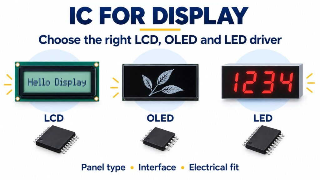
An IC for display applications translates host commands or image data into signals a display can use. The correct device depends on the panel technology: LED displays need current drive, segment LCDs need matched waveforms, and graphic modules need a compatible controller or interface. Identify the exact panel before selecting the IC.
For an OEM design, the first question is whether you are buying bare display glass, a display module with an integrated controller, or discrete LEDs. That decision determines which functions belong in your BOM and which are already included. This guide explains the differences, gives sourced component examples, and shows what to check before ordering.
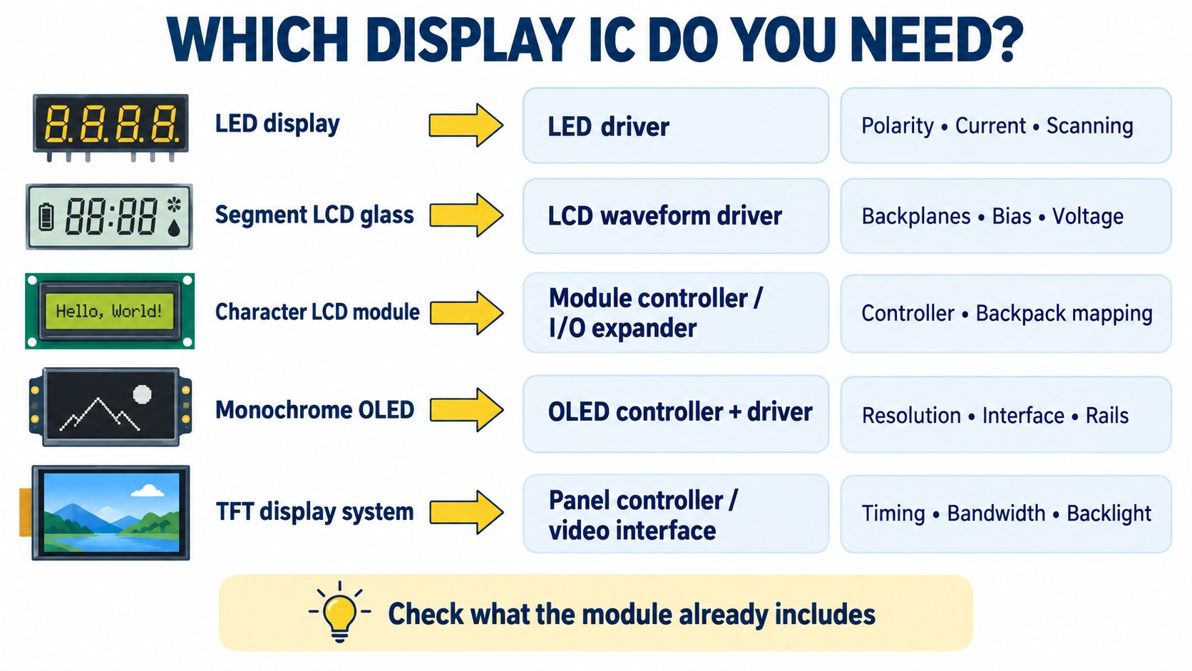
Which IC does your display need?
Start with the display technology and the functions already inside the module. A familiar part number is useful only after the panel's electrical requirements, interface and drive arrangement are known.
| Your display | IC function to look for | Documented example | First compatibility check |
|---|---|---|---|
| Common-cathode numeric LEDs or a small LED matrix | Segment current drive and multiplex scanning | MAX7219 / MAX7221 | LED polarity, digit count and logic thresholds |
| Common-anode seven-segment digit with BCD inputs | BCD decoding and segment current sinking | SN74LS47 | Current-limiting resistors and any external digit switching |
| Multi-channel LEDs with host-controlled scanning | Constant-current sink outputs | TLC59283 | Row-drive circuit, current budget and scan timing |
| Low-multiplex segment LCD glass | LCD bias and segment/backplane waveforms | PCF85176 | Glass segment map, backplanes, bias and LCD voltage |
| Character LCD module with an I2C backpack | Interface expansion to the module's controller | PCF8574 I/O expander | Backpack wiring and the actual LCD controller |
| Small monochrome OLED panel or module | OLED controller with segment/common drive | SSD1306 | Actual controller, panel size and module wiring |
| TFT system with a DSI host and LVDS panel | Video-interface conversion, where required | SN65DSI83 | DSI/LVDS mode, lane arrangement and panel timing |
These examples serve different electrical architectures. Their names are starting points for documentation review, rather than a list of interchangeable replacements.
What is the difference between a display driver and a display controller?
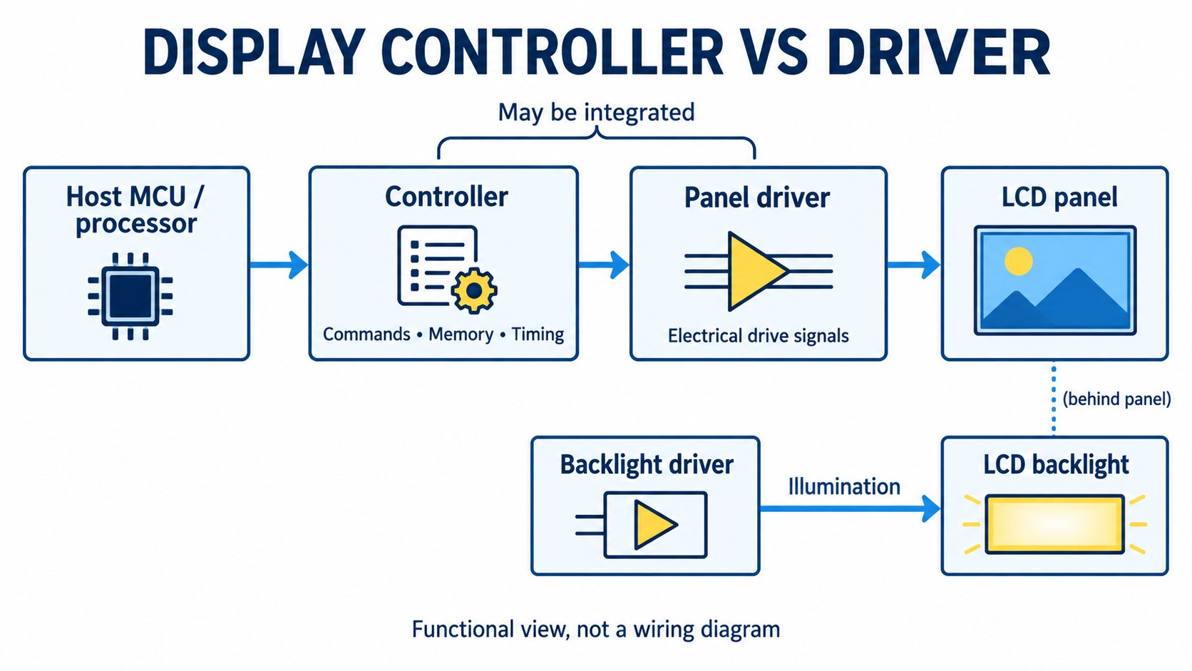
A display driver generates the electrical outputs needed by LEDs or display electrodes. A display controller interprets commands, manages addressing or memory, and coordinates updates. One IC can integrate both functions: Solomon Systech describes the SSD1306 as an OLED driver with a controller and display RAM. SSD1306 manufacturer documentation.
Keep three other roles separate:
- An interface bridge converts a supported video link into another supported link. TI's SN65DSI83 converts MIPI DSI video to LVDS; it does not make arbitrary panels compatible. TI SN65DSI83.
- A backlight driver regulates an LCD's illumination. It does not write the image pixels.
- A touch controller reads touch input. It is a separate function from producing the displayed image.
A visible IC on a breakout board may provide voltage regulation or interface expansion while the display controller is bonded to the glass or flex. Read the complete module schematic and panel specification before adding another controller.
How do you choose an LED display driver IC?
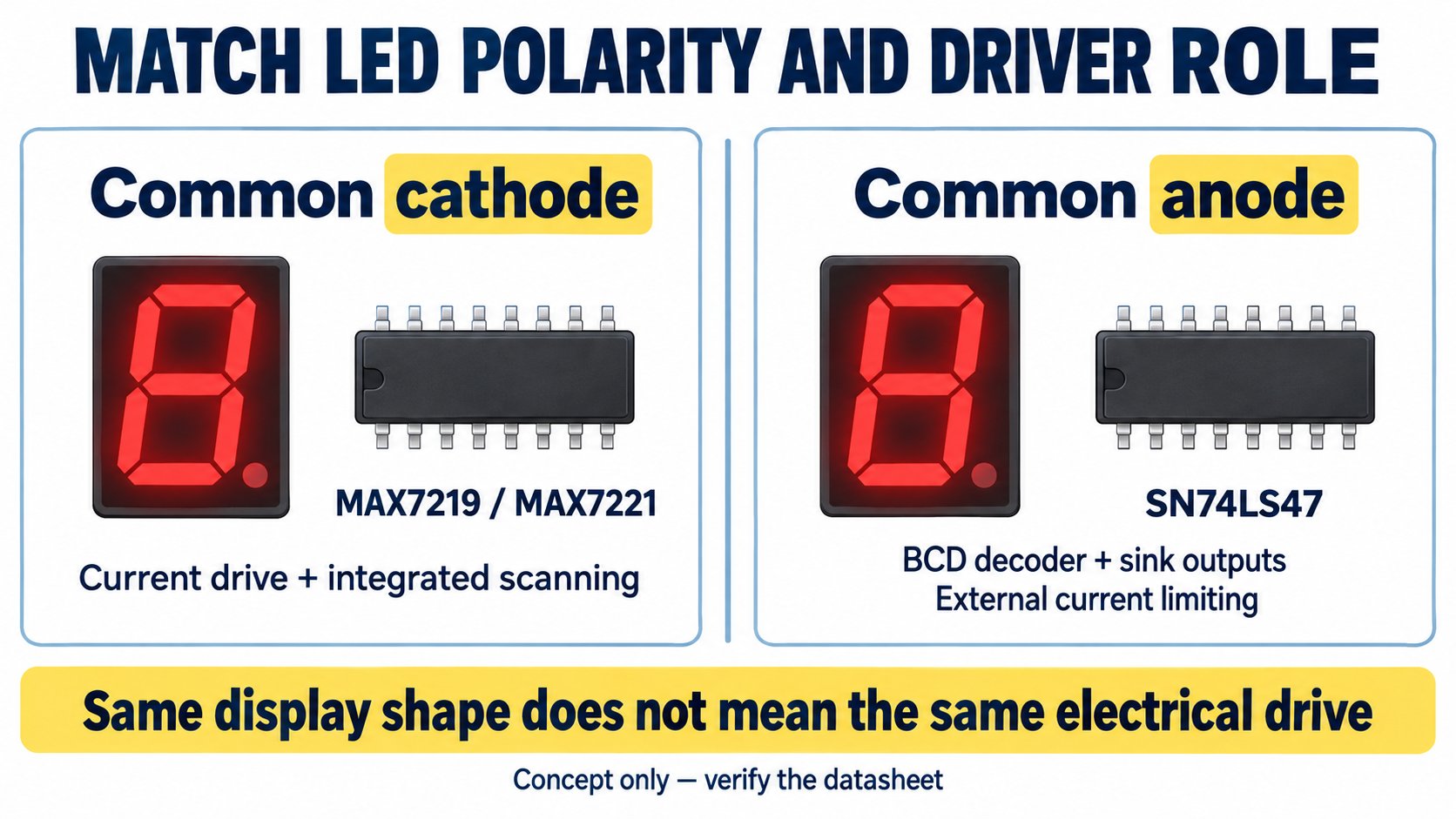
For LEDs, establish polarity, current, channel count and scan architecture first. A seven-segment decoder, a driver with automatic scanning, and a bank of constant-current outputs solve different problems.
Seven-segment drivers: check common anode versus common cathode
The MAX7219/MAX7221 family drives common-cathode LED displays and supports up to eight numeric digits or 64 individual LEDs. Its scanning and display-memory functions reduce the host's control work. ADI specifically identifies the MAX7221 as SPI-compatible; compare the two devices' serial timing instead of assuming every interface detail is identical. ADI MAX7219/MAX7221 overview.
The SN74LS47 has active-low, open-collector outputs for common-anode indicators. A design using this decoder must provide suitable LED current limiting and handle any multiplexed digit selection separately. A MAX7219 and an SN74LS47 therefore cannot be exchanged simply because both operate seven-segment displays. TI SN74LS47 documentation.
LED matrix drivers: check what scanning remains outside the IC
The TLC59283 provides 16 constant-current sink channels controlled through a serial interface. TI specifies current capability of 35 mA when VCC is at or below 3.6 V, and 45 mA above 3.6 V within its permitted supply range. Those limits depend on operating conditions and thermal constraints. TI TLC59283.
A current-sink driver alone does not supply a complete matrix controller. Identify the row-switching circuit, blanking sequence and brightness-control method. In a multiplexed design, peak LED current and average LED current differ; neither the LED pulse rating nor the driver's thermal limit can be skipped.
For a large LED video panel, also specify the scan ratio, grayscale method and receiving-controller requirements. A small numeric-display driver is not a universal choice for a signage module.
What should you check for LCD and OLED displays?
LCD and OLED are different technologies, and even two displays within one technology may require different drive arrangements. Separate raw glass from an assembled module before comparing controller ICs.
Segment LCD glass requires the correct bias and backplane drive
The PCF85176 supports up to 40 segment outputs and four backplanes, with selectable static and multiplexed drive configurations. Its 40 × 4 capability refers to segment/backplane addressing, not a 40-by-4-pixel graphic screen. NXP PCF85176 datasheet.
Obtain the glass electrode map, required LCD voltage, bias ratio and multiplex duty. Match those requirements to the driver's waveform options. A device described as an “LCD driver IC” is not automatically compatible with every LCD panel.
A PCF8574 backpack is not the LCD's pixel driver
The PCF8574 is an I2C I/O expander. In a supported character-LCD arrangement, it carries control and data signals to the LCD controller; the expander itself does not contain the character-generation and panel-driving functions. TI PCF8574, Microsoft's character-LCD integration example.
Before reusing firmware, confirm the backpack pin mapping, module controller and voltage levels. “I2C LCD” describes the exposed interface, rather than one guaranteed controller implementation.
OLED controller capability is not the module specification
Solomon Systech specifies the SSD1306 for a 128 × 64 monochrome OLED matrix and lists I2C, SPI and parallel interface options. A particular module may expose only one option, use a smaller panel, or strap configuration pins internally. SSD1306 product documentation.
A 128 × 64 monochrome image needs 1,024 bytes when stored at one bit per pixel: 128 × 64 ÷ 8. This is an image-buffer calculation, not the application's complete RAM requirement.
Inspect the module's regulator, pull-ups and power circuit before applying a supply voltage. A supply accepted by a finished module does not establish the safe supply or input level for the bare controller.
How do you match the display interface and bandwidth?
Match the host's available interface to the display's documented input, then check the actual update workload. A shared connector label or the word “SPI” does not prove compatible commands, timing or electrical levels.
| Interface or connection | Typical decision to make | What must be verified |
|---|---|---|
| I2C | Is command or small-image traffic sufficient? | Address, bus frequency, pull-up voltage and transaction format |
| SPI or another clocked serial connection | Can updates finish within the required interval? | SPI mode where applicable, clock limit, data framing and chip-select behavior |
| Parallel command/data bus | Does the host have the required pins and timing? | Bus width, write/read strobes and controller commands |
| RGB pixel bus | Can the host supply a continuous pixel stream? | Pixel clock, synchronization, porches and frame-buffer needs |
| MIPI DSI or LVDS | Do the host and panel support the same video architecture? | Mode, lanes, mapping, signaling and permitted timing |
The table is a selection checklist; it does not establish that every controller supports every listed interface. For a documented conversion example, review the SN65DSI83's supported DSI input and LVDS output modes. TI interface-bridge documentation.
Calculate the image payload before choosing the link
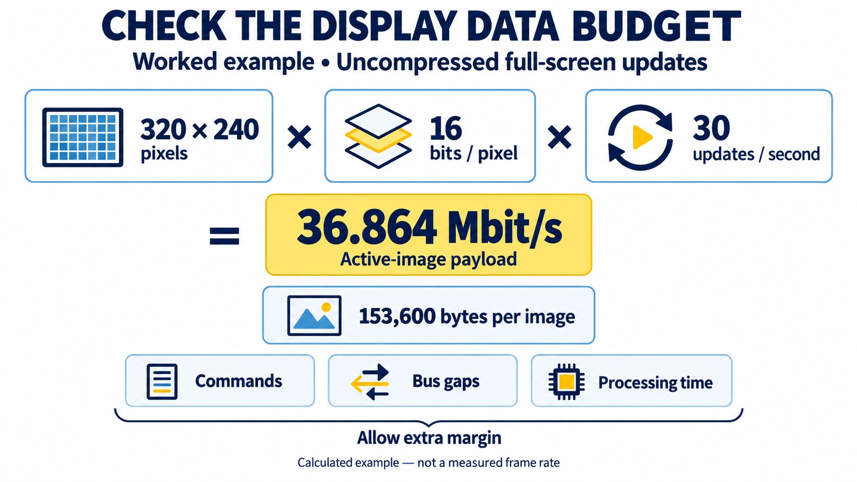
For uncompressed full-screen updates, the active-image payload is:
width × height × bits per pixel × updates per second
For a hypothetical 320 × 240 display at 16 bits per pixel and 30 full-screen updates per second:
320 × 240 × 16 × 30 = 36,864,000 bit/s = 36.864 Mbit/s
One full image occupies 153,600 bytes. These calculated figures exclude commands, bus gaps, rendering time and any required video blanking. A nominal 40 MHz, single-bit SPI clock leaves limited theoretical margin for this workload; this arithmetic does not demonstrate an achievable frame rate. Partial updates can reduce the payload when the controller and application support them.
Compare logic levels separately from supply voltages
Check the host's guaranteed output levels against the receiver's input thresholds under the intended supplies and temperature range. Also check any return signals and I2C pull-ups. A working prototype at room temperature does not establish guaranteed logic margin.
For the MAX7219/MAX7221, use the electrical-characteristics and timing tables to qualify a connection to a 3.3 V host. Do not infer compatibility from the existence of a serial interface. Manufacturer datasheet.
Which mistakes cause display IC selection problems?
Most avoidable errors come from qualifying only one part of the display system. Use these checks before approving an IC or module change.
| Selection mistake | Why it creates a problem | Better verification |
|---|---|---|
| Choosing by screen size alone | Size does not identify controller commands or electrode drive | Obtain the exact panel/module part number and datasheet |
| Treating every LED driver as a display controller | Current regulation may leave scanning and image handling to the host | Document the complete control and current path |
| Ignoring LED common-anode/common-cathode polarity | The output architecture can be wrong for the display | Check the LED assembly and driver output arrangement |
| Assuming an I2C backpack drives LCD glass | An I/O expander still depends on a separate LCD controller | Verify the controller and backpack signal mapping |
| Reusing code from a visually similar module | Initialization, memory addressing or panel timing may differ | Test the actual supplied revision and command sequence |
| Approving a replacement from package size alone | Matching footprints do not establish electrical or firmware compatibility | Compare pinout, rails, outputs, commands and startup behavior |
For production sourcing, record the approved IC ordering code, panel revision and initialization settings together. That record gives engineering and purchasing the same acceptance baseline.
What should you include in a display IC RFQ or BOM?
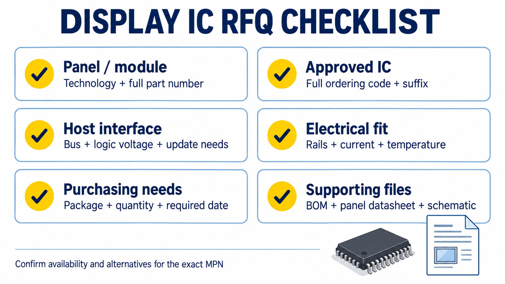
Provide the exact IC ordering code when it is already approved. If you need help identifying a suitable family, provide the display and host requirements so the request can be evaluated against documented constraints.
Include:
- Display identification: technology, panel/module manufacturer and full part number.
- Drive arrangement: common anode/common cathode, segment/backplane count, or pixel resolution.
- System interface: host MCU/processor, exposed bus, logic voltage and required update behavior.
- Electrical requirements: permitted rails, LED current where applicable, brightness-control method and operating temperature.
- Procurement details: full IC MPN with suffix, package, quantity, required date and approved-alternative policy.
- Supporting files: BOM, schematic excerpt, panel datasheet and approved firmware or initialization revision where relevant.
Ask for current availability, lead time, price and traceability information for the specific ordering code. A controller-family name or a development-board listing is not a complete production purchasing specification.
Browse integrated circuits and LED character and dot-matrix displays to review the relevant component categories. For an approved part or a multi-item project, request a quote or upload your BOM with the display requirements above.
Frequently asked questions
What is an IC for display?
An IC for display is a chip used to control image data, generate display-drive signals, or support a specific part of a display system. Its function depends on the technology and assembly. An OLED controller, LED current driver and video bridge therefore serve different roles.
Which IC is suitable for a seven-segment display?
For documented examples, the MAX7219/MAX7221 family supports common-cathode displays with integrated scanning, while the SN74LS47 decodes BCD for common-anode indicators. Check polarity, current limiting, digit count and logic levels before choosing. ADI, TI.
Is PCF8574 an LCD driver IC?
It is an I2C I/O expander. In a character-LCD backpack, it connects the host to the LCD's own controller through parallel control/data signals. It does not replace a controller that drives raw LCD glass. TI PCF8574.
Can the same IC drive LCD and OLED displays?
Do not assume so. A segment-LCD device such as PCF85176 and an OLED controller such as SSD1306 provide different panel-drive functions. Use the exact panel requirements and manufacturer compatibility documentation to select the device. NXP, Solomon Systech.
Can a 3.3 V microcontroller control a 5 V display driver?
Only when the host's guaranteed logic levels meet the driver's thresholds and all pins remain within their allowed voltages. Check both directions, pull-up rails and startup conditions. Use appropriate translation when the electrical specifications do not establish a safe connection; a successful bench test alone is insufficient.
Manufacturer references and design documentation
- Analog Devices MAX7219/MAX7221 overview: display type, supported counts and integrated functions.
- MAX7219/MAX7221 datasheet: electrical characteristics, serial timing and application details.
- TI SN74LS47: BCD decoding and common-anode output architecture.
- TI TLC59283: constant-current outputs and operating conditions.
- NXP PCF85176 datasheet: segment/backplane configuration, LCD bias and drive waveforms.
- TI PCF8574 and Microsoft's LCD integration tutorial: I/O expansion and a character-module implementation.
- Solomon Systech SSD1306: OLED controller capability and interface options.
- TI SN65DSI83: the scope of a DSI-to-LVDS bridge.