
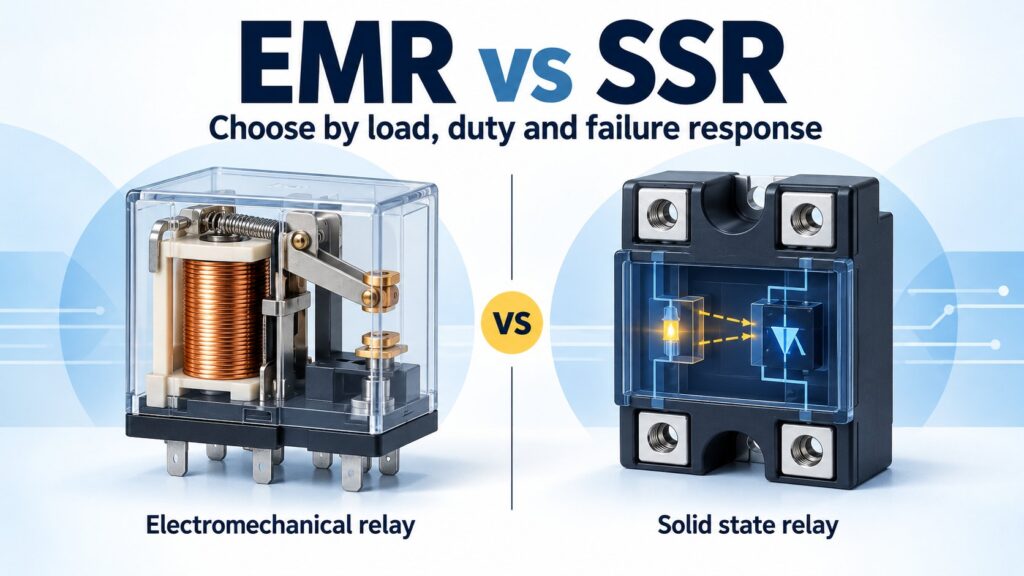
Choose an electromechanical relay (EMR) when contact configuration, very low off-state current, and infrequent switching matter most. Choose a solid-state relay (SSR) when frequent, quiet switching justifies its output losses and protection requirements. Start with the load voltage and current waveform—not the current printed on the relay housing.
The difficult part of an EMR vs SSR comparison is that “SSR” covers several different output technologies. A zero-cross AC power relay, a DC MOSFET module, and a small PhotoMOS relay cannot share one speed, leakage, or thermal specification. This guide separates those cases, then turns the differences into a selection checklist.
EMR vs SSR at a glance
| Selection question | Electromechanical relay | Solid-state relay |
|---|---|---|
| How does it switch? | A coil moves physical contacts. | A semiconductor output controls conduction. |
| How fast can it respond? | Operate, release, and bounce times depend on the relay. | Output topology and trigger mode govern timing; AC zero-cross types wait for the waveform. |
| What limits operating life? | Mechanical wear and load-dependent contact erosion or welding. | Electrical stress, temperature, thermal cycling, and component aging. |
| What happens while ON? | Contact resistance dissipates power; an energized coil may add heat. | SCR/TRIAC voltage drop or MOSFET resistance produces heat. |
| What happens while OFF? | Open contacts provide a physical gap; external suppression may still pass current. | Off-state leakage must be checked against the load's release threshold. |
| What about sound? | Mechanical actuation can produce a click. | No mechanical contact noise or contact bounce. |
| Which contact forms are available? | Normally open (NO), normally closed (NC), and changeover configurations, including multiple poles. | Many power models are normally open; other forms exist in specific families. |
| What determines installed cost? | Relay, socket, coil drive, and expected replacement work. | Relay, heat removal, protective devices, wiring, and required disconnect. |
This table is a selection framework, not a set of guaranteed ratings. Omron's technology comparison explains the basic contact/semiconductor tradeoffs; individual datasheets set the operating limits.
How the two relay technologies work
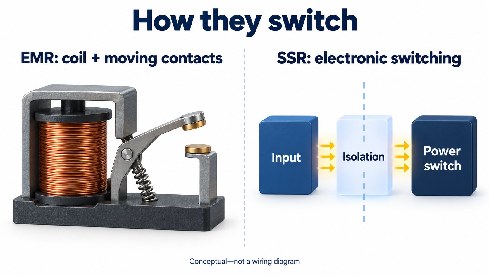
An electromechanical relay uses magnetic force from an energized coil to move an armature and change the state of metal contacts. A conventional non-latching relay returns when coil drive is removed; latching types require a different control sequence. The contact circuit and coil circuit have separate ratings. NI's relay guide describes these mechanisms in the context of test-system switching.
A solid-state relay has no moving output contacts. AC power models commonly use a TRIAC or opposed silicon-controlled rectifiers (SCRs); other designs use MOSFETs or transistors. Optical isolation is common, but it is not universal: capacitive and inductive isolation also exist. Texas Instruments' SSR overview distinguishes these isolation methods and their aging mechanisms.
First separate the control input from the load output
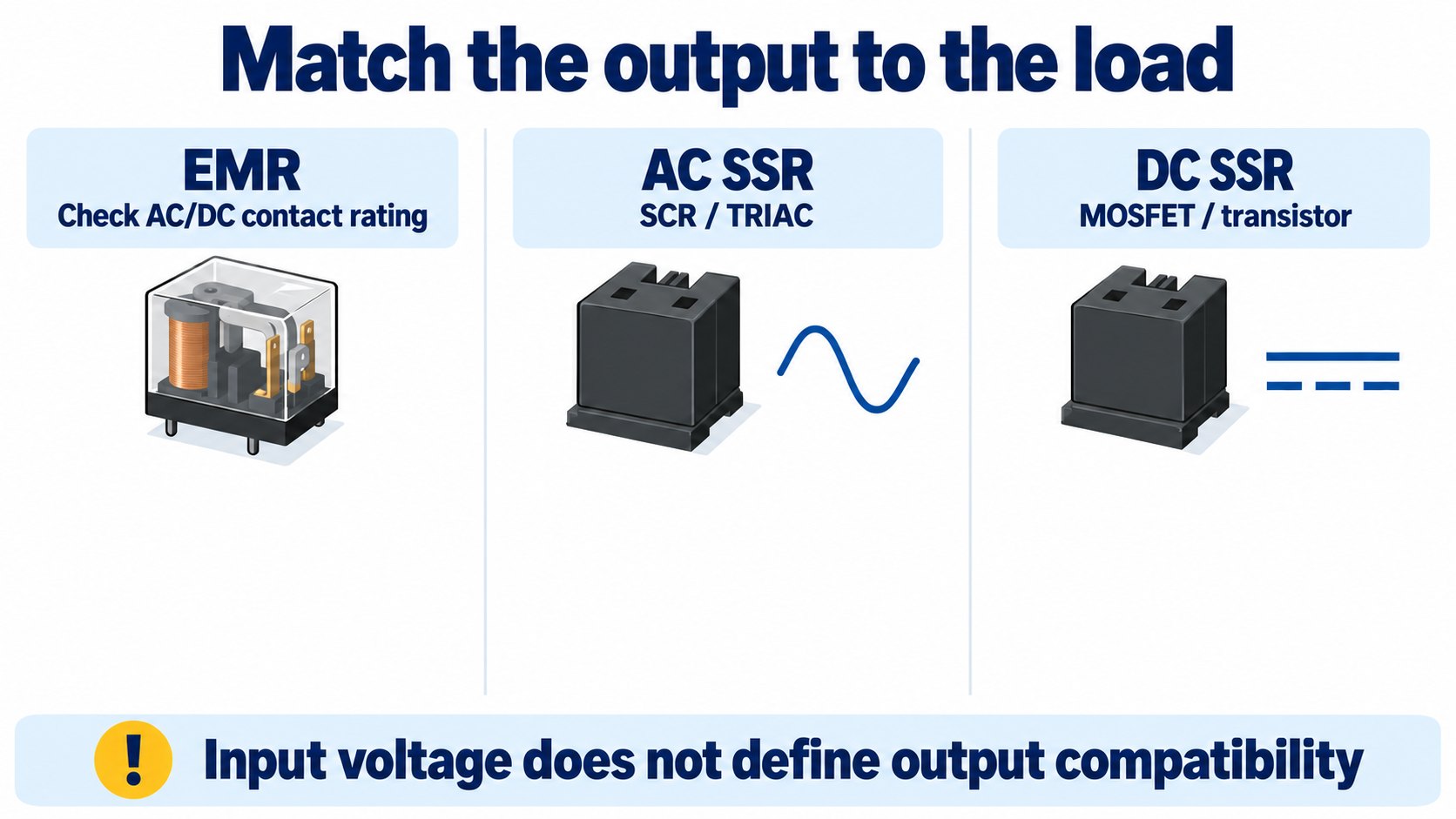
A DC control input does not make a relay suitable for a DC load. A module can accept a low-voltage DC control signal while switching a mains AC load. Read the input and output specifications separately.
An ordinary SCR/TRIAC AC SSR relies on load current falling below its holding current to turn off. It cannot provide normal commanded interruption of a steady DC load. Omron FAQ02101 explains this restriction. For DC switching, select an explicitly DC-rated MOSFET or transistor output and verify polarity. Some back-to-back MOSFET relays support both AC and DC within their stated limits; a generic DC module should not be assumed to do so. See Omron's output-device guidance.
An EMR also needs a suitable DC breaking rating. Its AC current rating is not permission to interrupt the same current at the same DC voltage. Before replacing either technology, compare the exact load rating, pole arrangement, mounting, terminal layout, and control requirements.
Switching speed: zero-cross is not instant switching
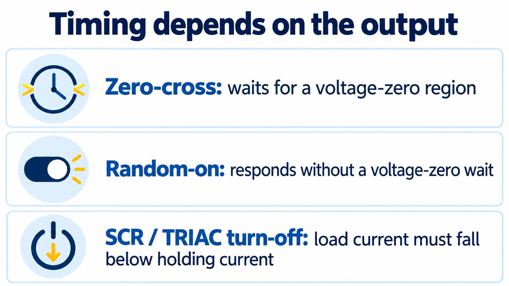
A zero-cross AC SSR waits until the voltage across its output is near zero before initiating conduction. This is often useful for time-proportioned resistive heating because it reduces switching disturbance. A random-turn-on SSR does not impose that voltage-zero wait, making it a candidate for phase-angle control when paired with a suitable controller.
Turn-off is a separate event: an SCR/TRIAC output must regain its blocking state as load current falls below holding current. With an inductive load, voltage and current zero crossings occur at different times. Therefore, “zero-cross” does not mean that both transitions occur at voltage zero. Omron's SSR terminology guide explains the switching behavior.
For an ideal 50 Hz waveform, one half-cycle is 10 ms; at 60 Hz it is 8.33 ms. Those values describe waveform timing, not a universal guaranteed relay response. Add the device's specified detection and switching delays. Do not infer kilohertz load switching from the absence of mechanical contacts.
Mechanical timing also varies. NI gives 5–15 ms as a typical switch-and-settle range for the EMRs discussed in its test-equipment guide; that is not a universal operate/release specification. Check each candidate's datasheet and include bounce where the receiving circuit is sensitive to it.
Heat and lifetime: calculate the operating conditions
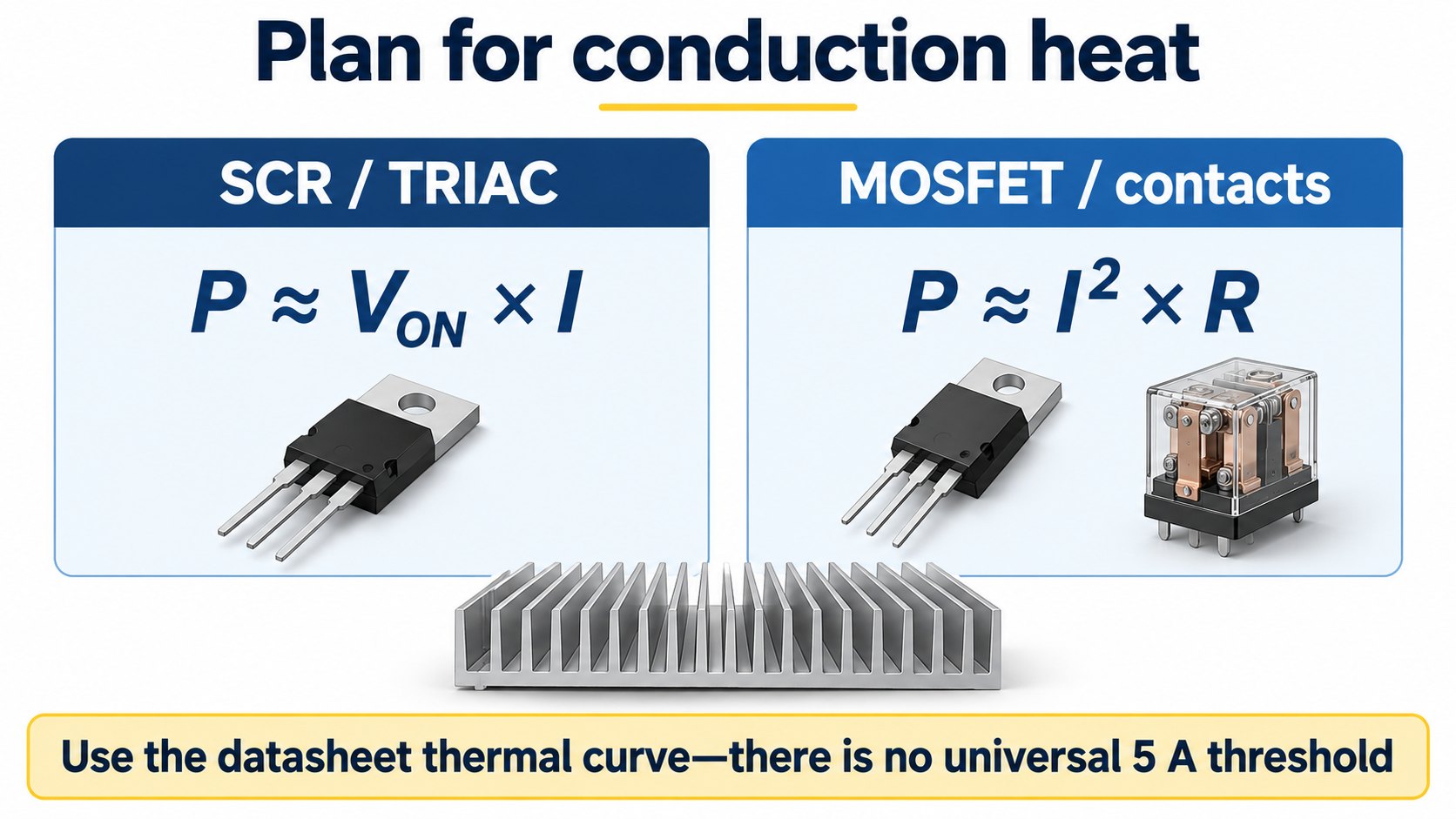
There is no universal 5 A threshold above which every SSR needs a separate heatsink. The answer depends on output losses, ambient temperature, enclosure airflow, mounting, thermal interface, and the manufacturer's derating curve. An integrated heatsink does not remove these limits.
For an SCR/TRIAC output, a constant-drop estimate is P ≈ VON × I. For a resistive output path, including MOSFETs or closed contacts, use P ≈ IRMS² × R. For AC semiconductor losses, the manufacturer's dissipation curve is preferable to a single voltage-drop shortcut; waveform shape and current-dependent voltage drop matter. Opto 22's SSR datasheet, heat-sink calculation section shows how dissipation and thermal resistance enter the thermal budget.
A worked thermal-budget example
Assume a candidate's loss curve gives 12 W at the intended operating point. Assume maximum local ambient is 45°C, the design junction target is 105°C, junction-to-case thermal resistance is 1.0°C/W, and case-to-sink resistance is 0.2°C/W.
RθSA ≤ (105 − 45) / 12 − 1.0 − 0.2 = 3.8°C/W
The calculated heatsink-to-ambient ceiling, RθSA, is 3.8°C/W. The sink would need a value below that ceiling in its actual installation, with design margin. These are assumed calculation inputs, not specifications for any product in the table below. The simple steady-state model excludes transient heating and neighboring heat sources; a real design must also meet the manufacturer's case-temperature and mounting limits.
An EMR also dissipates heat. For example, an assumed 10 mΩ contact path carrying 10 A dissipates 1 W, before coil and terminal losses. Rising contact resistance changes that result. TE's contact-life guidance explains how heating and material transfer affect contacts.
Compare electrical endurance, not a fixed life multiplier
An EMR's mechanical endurance may be measured without the electrical load that erodes its contacts. Use electrical endurance at the relevant voltage, current, load type, and switching rate; Panasonic explains the two endurance tests. SSRs avoid contact wear, but they still have failure and aging mechanisms; TI's overview includes optical degradation and insulation-related mechanisms. A claim such as “200 times longer life” is not a general design rule.
For a simple duty estimate, an assumed two complete ON/OFF cycles per minute over 16 hours per day and 250 days per year produces 480,000 cycles per year. Compare that workload with documented endurance conditions. This estimates demand on the switch; it does not predict field lifetime.
Off-state leakage and minimum load are different checks
Leakage current flows while the output is commanded OFF. Minimum load current is the load-current condition needed for normal switching. A TRIAC/SCR's holding current is one underlying device requirement, not a universal 0.1 A specification for every SSR. MOSFET outputs do not need thyristor holding current. Omron FAQ02109 explains the distinction.
An LED that glows faintly or an input that remains asserted does not by itself prove that the SSR has failed short. Compare the specified maximum leakage, including any external snubber path, with the connected device's OFF threshold. Leakage also varies by technology: low-leakage MOSFET relays and mains power SSRs should not be treated as one category.
Check the control side too. Residual current from the controller can keep an SSR input active after the controller appears to turn off. Omron's troubleshooting guidance separates input leakage, output leakage, and commutation problems. A load-specific bleeder may help, but it needs its own voltage, power, and thermal checks; it is not a substitute for a safe disconnect.
For an EMR, the open contact gap removes the semiconductor leakage mechanism. Avoid promising literal zero leakage for the complete assembly: suppression components and other parallel paths can still carry current.
Design for inrush, transients, and a failed-ON output
Size the switching path for startup and fault behavior as well as continuous current. A non-repetitive surge rating is not automatically a repetitive inrush rating. Omron distinguishes these in its SSR terminology and rating guidance. Record the load's inrush amplitude, duration, repetition rate, and starting conditions before choosing a derating factor.
Transformer loads deserve particular care: zero-voltage turn-on can increase magnetizing inrush, and random turn-on can still occur at an unfavorable phase angle. TE's transformer-switching note explains why a heater-oriented trigger choice should not be copied into every inductive-load design.
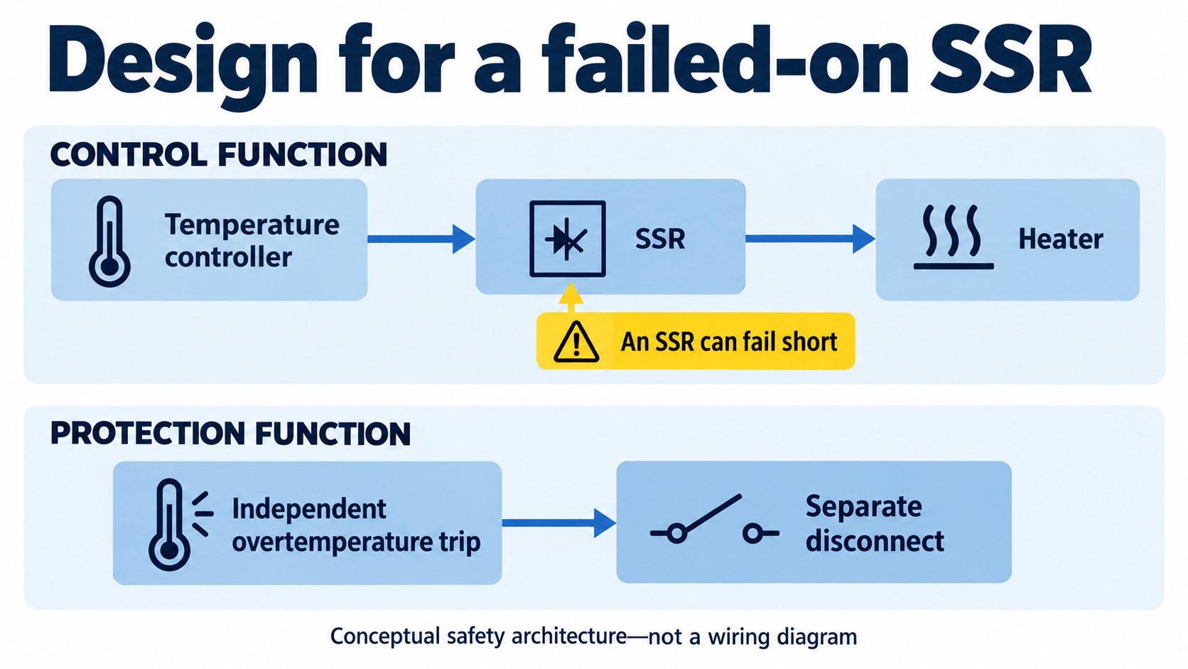
Protection has separate jobs. A suitably rated RC network or voltage clamp can limit switching transients; coordinated overcurrent protection addresses excess current. Neither function alone guarantees removal of heater power after an SSR fails conductive. Component values and fuse coordination must come from the device and load requirements, not a generic “ten-times-current” rule.
For DC inductive loads, a flyback or clamping network must suit the required release time and permissible voltage. AC loads need an AC-suitable suppression approach; an ordinary flyback diode cannot simply be copied across an AC load. Our TVS diode guide explains the separate checks for stand-off voltage, clamping voltage, and surge energy.
An SSR can fail short, and an EMR can weld closed. Omron identifies short-circuit failure as the principal SSR failure mode and calls for an additional means of interrupting the load. A heater system may therefore use an independent overtemperature trip operating a separate disconnect, alongside its normal temperature controller and SSR. The disconnect, sensing, and fault response must be appropriate to the equipment; adding an arbitrary relay does not establish a safety function. See Omron's SSR safety precautions.
Match the application to the right checks
| Application | Starting point | Check before committing |
|---|---|---|
| Frequent time-proportioned resistive heating | Zero-cross AC SSR | Heat removal, minimum load, controller cycle time, and independent overtemperature shutdown. |
| Infrequent multipole changeover | EMR with the required contact form | NO/NC ratings, switching sequence, coil drive, and electrical endurance. |
| Low-current sensing or PLC interface | Signal relay or suitable low-leakage solid-state output | Load OFF threshold, minimum switching load, contact material, and input compatibility. |
| DC actuator or PWM load | Appropriate DC semiconductor output or a load-rated EMR for infrequent operation | Polarity, inductive energy, switching-frequency limits, and release time. |
| Transformer or capacitive-input power supply | A device explicitly suitable for that load | Measured or documented inrush waveform and switching strategy. |
No moving contacts can be useful where vibration or acoustic noise matters, but SSR construction alone does not establish automotive, medical, moisture, or hazardous-location suitability. Check the exact product and equipment requirements. Ordinary SSR precautions can explicitly prohibit flammable atmospheres, excessive dust, or condensation; a lack of contact arcing is not explosion-proof approval.
Representative models: what the complete part number changes
The following examples illustrate specification boundaries, rather than a current-stock shortlist. Check the linked manufacturer's document for the complete load and environmental ratings.
Ratings below retain the conditions in the cited documents; different rating conventions must not be merged.
| Complete example | Control and switching specification | Selection lesson |
|---|---|---|
| Schneider RXM4AB2B7 | 24 V AC coil; four changeover contacts; LED and lockable test button. The cited IEC values distinguish 6 A NO from 3 A NC at 250 V AC. | Check which contact carries the load. The linked archived datasheet is dated October 24, 2017. |
| Schneider RXM2AB1B7 | 24 V AC coil; two changeover contacts. The manufacturer sheet lists 12 A NO / 6 A NC at 250 V AC, and separately 10 A continuous output current. | A 12 A headline is not an unrestricted continuous-load rating. This manufacturer PDF is hosted by RS. |
| Finder 13.31.9.024.4300 | 24 V DC supply; one NO contact; rated contact specification 12 A / 250 V AC. | Its 400 V AC maximum switching voltage is not a 12 A / 400 V AC load rating. |
| Omron G3NA-210B-UTU DC5-24 | Zero-cross AC SSR: rated input 5–24 V DC; rated output 24–240 V AC. At 40°C, 0.1–10 A with the specified heatsink; 0.1–4 A without it. | Retain the input suffix and cooling conditions. DIN mounting needs the appropriate separately ordered accessory. |
| Schneider SSD1A360BDC3 | Single-phase 60 A zero-voltage-switching model; input 4–32 V DC; output 48–600 V AC; DIN mounting and integrated heatsink. | Read ambient-temperature and spacing derating. The manufacturer catalogue, hosted by DDS identifies the integrated cooling arrangement. |
For the Omron example, the lineup page distinguishes the input options and separately ordered mounting accessories. Confirm the current full-order-code datasheet before purchase.
What to include in a relay RFQ or replacement review
Use this sequence to turn a generic relay request into a reviewable specification:
- Identify the load: AC or DC voltage, frequency, steady current, and load type.
- Describe switching stress: inrush waveform, repetition rate, duty cycle, and required response time.
- State control requirements: voltage range, available drive current, active polarity, and OFF-state leakage.
- Specify the switching arrangement: poles, NO/NC/changeover form, and any required interlocking or disconnection behavior.
- Define the installation: ambient temperature, enclosure, mounting, terminal layout, available heatsink or airflow, and environmental requirements.
- Provide the complete manufacturer part number and quantity: include input-voltage and option suffixes, plus the datasheet revision and applicable approval requirements.
Browse the relay category or submit an RFQ/BOM with these details. Availability, pricing, lead time, and application suitability require confirmation for the exact item.
Frequently asked questions
Can I replace an EMR with an SSR without changing the circuit?
Do not assume a direct replacement. Check output AC/DC compatibility, leakage, minimum load, losses, contact form, control drive, and failed-ON behavior. A matching nominal current rating does not establish compatibility.
Does zero-cross switching always reduce inrush?
No. Its effect depends on the load. Resistive heaters and transformers do not have the same starting behavior. Select the trigger strategy from the load requirements rather than treating zero-cross or random-turn-on as universally preferable.
Can a relay's input LED prove that the load is disconnected?
No. An input indicator reports a control condition, not verified interruption of the load path. Leakage, a failed semiconductor output, or welded contacts must be considered separately.
Are IEC 61810-1 and IEC 62314 product certifications?
They are standards with defined scopes. A reference to a standard does not prove that an individual relay is certified or that a completed machine meets its requirements. Obtain the relevant manufacturer's declarations or certification records for the exact device and application.
The IEC public catalogue describes IEC 61810-1 for electromechanical elementary relays and IEC 62314 for solid-state relays. These catalogue summaries establish scope only; this review did not examine the paid standards in full.