
Table of Contents
AMS1117 3.3V Circuit: Pinout, Wiring and Design Checks
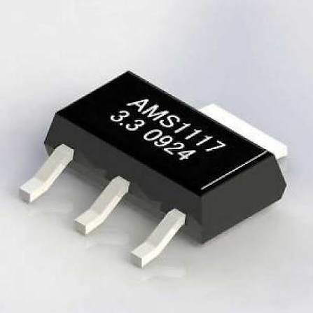
An AMS1117 3.3V circuit is a simple linear regulator circuit that converts a higher DC input, commonly 5V, into a regulated 3.3V rail for microcontrollers, sensors, logic ICs and small embedded boards. The basic circuit only needs the AMS1117-3.3 regulator plus input and output capacitors, but the real design checks are dropout voltage, heat dissipation, capacitor placement, pinout, package and load current.
The two reference articles both use a practical structure: introduce AMS1117-3.3, explain pinout and packages, show the wiring circuit, list applications, then end with precautions and FAQ. This guide follows that structure but adds engineering checks that matter before a board or BOM is approved.
Quick Circuit Summary
| Circuit item | Recommended check |
|---|---|
| Input source | Usually 5V DC for a 3.3V output |
| Regulator | AMS1117-3.3 fixed-output LDO |
| Pin 1 | GND on common fixed-output SOT-223 AMS1117-3.3 layouts |
| Pin 2 / tab | VOUT on common fixed-output SOT-223 layouts |
| Pin 3 | VIN on common fixed-output SOT-223 layouts |
| Input capacitor | Commonly 10uF plus optional 0.1uF ceramic close to VIN and GND |
| Output capacitor | Commonly 10uF to 22uF, with ESR and type checked against the exact datasheet |
| Main formula | Power dissipation = (VIN – 3.3V) x load current |
| Main risk | The regulator overheats before it reaches the headline 1A current |
Basic AMS1117-3.3 Circuit
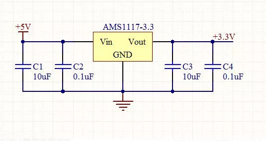
Use this as the starting point for a fixed 3.3V output circuit:
          +5V DC input
              |
              |       C_IN
              +------||------+
              |     10uF     |
              |              |
           VIN pin 3         |
        +------------+       |
        | AMS1117-3.3|       |
        |            |       |
GND ----| pin 1      |       |
        |            |       |
        | pin 2 VOUT |-------+---- +3.3V output
        +------------+       |
              |              |
              |       C_OUT  |
              +------||------+
                    10uF-22uF
              |
             GND
For a PCB layout, place the input capacitor close to VIN and GND, and place the output capacitor close to VOUT and GND. Keep the high-current paths short and give the SOT-223 tab enough copper area for heat spreading.
AMS1117-3.3 Pinout
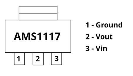
For the common fixed-output SOT-223 AMS1117-3.3 regulator, the usual pinout is:
| Pin | Function | Connection in a 3.3V circuit |
|---|---|---|
| Pin 1 | GND | Connect to system ground |
| Pin 2 | VOUT | Connect to the 3.3V rail and output capacitor |
| Pin 3 | VIN | Connect to the input supply and input capacitor |
| Tab | Usually VOUT | Connect to the output copper area if the footprint expects it |
Do not skip the datasheet check. AMS1117, LM1117, LD1117, NCP1117 and other 1117-style regulators can look interchangeable, but package, pinout, tab connection, current rating and capacitor requirements may differ.
How the AMS1117 3.3V Circuit Works
AMS1117-3.3 is a fixed-output low-dropout linear regulator. Internally, it compares the output voltage against a reference and adjusts a pass transistor so the output stays near 3.3V when input voltage or load current changes.
Because it is a linear regulator, it does not step down voltage the way a buck converter does. The extra voltage becomes heat:
Power dissipation = (VIN – VOUT) x ILOAD
For a 5V input, 3.3V output and 300mA load:
(5V - 3.3V) x 0.3A = 0.51W
For a 1A load:
(5V - 3.3V) x 1A = 1.7W
That is why a circuit can be electrically correct but still fail thermally.
Step-by-Step Wiring Guide
1. Confirm the Input Voltage
For a 3.3V output, a 5V DC input is the common choice. The input must stay above the output voltage plus the regulator dropout voltage under the expected load. A weak battery or long cable can sag below the required headroom and cause the 3.3V output to drop.
2. Connect Ground First
Connect AMS1117 pin 1 to the system ground. The input capacitor, output capacitor and load must share the same ground reference. A poor ground layout can create ripple, noise or unstable regulation.
3. Connect VIN
Connect pin 3 to the input supply. Add the input capacitor close to pin 3 and ground. A 10uF capacitor is commonly used, and a 0.1uF ceramic capacitor can help with high-frequency noise.
4. Connect VOUT
Connect pin 2 to the 3.3V rail. Add the output capacitor close to VOUT and ground. Many AMS1117-style circuits use 10uF to 22uF output capacitance, but the exact value, dielectric and ESR should follow the selected manufacturer datasheet.
5. Check the Load Current
List every load on the 3.3V rail: MCU, sensor, display, RF module, pull-up networks and any transient load. Add margin. If the continuous current is high, calculate heat before assuming the AMS1117 can handle it.
6. Test Before Connecting Expensive Loads
Power the regulator without the target IC first. Measure the input voltage, output voltage, ripple and regulator temperature. Then connect the real load and repeat the test under the highest expected current.
Capacitor Selection Notes
The two reference articles correctly emphasize input and output capacitors, but production designs should go one step deeper:
| Capacitor point | Why it matters |
|---|---|
| Input capacitor close to VIN | Reduces input dips and cable or rectifier ripple |
| Output capacitor close to VOUT | Helps transient response and regulator stability |
| ESR requirement | Some 1117-style LDOs are sensitive to output capacitor ESR |
| Ceramic-only substitution | May not match older datasheet stability assumptions |
| Voltage rating | Use enough margin above the input or output voltage |
| Temperature behavior | Cheap capacitors can lose effective capacitance at temperature or DC bias |
For one-off prototypes, a 10uF input capacitor and 10uF to 22uF output capacitor often work. For production, qualify the capacitor type and ESR against the exact AMS1117-3.3 datasheet or approved alternative datasheet.
Thermal Design Checks
Thermal design is the most common weak point in AMS1117 3.3V circuits.
| Example | Heat in regulator | Practical meaning |
|---|---|---|
| 5V to 3.3V at 100mA | 0.17W | Usually easy on a reasonable PCB |
| 5V to 3.3V at 300mA | 0.51W | Needs copper area and temperature check |
| 5V to 3.3V at 500mA | 0.85W | Often too warm on small SOT-223 boards |
| 5V to 3.3V at 1A | 1.7W | Needs serious thermal review; a buck converter may be better |
| 12V to 3.3V at 300mA | 2.61W | Usually a poor use of AMS1117; use a switching regulator first |
If the input voltage is much higher than 5V, use a buck converter before the LDO or choose another power architecture. The AMS1117 is simple, but it is not efficient when the voltage drop is large.
Common Applications
An AMS1117 3.3V circuit is commonly used in:
- Arduino, STM32, ESP8266 and ESP32 support circuits when the thermal margin is acceptable.
- Sensor modules that need a simple 3.3V rail from 5V.
- Logic-level power rails on small embedded boards.
- USB-powered devices where a 5V rail is already available.
- Post-regulation after a switching supply when a quieter 3.3V rail is needed.
- Repair or replacement of existing 1117-style regulator footprints after pinout verification.
For battery-powered IoT devices, do not assume AMS1117-3.3 is the best choice. Many battery designs need a lower quiescent current LDO or a buck regulator.
AMS1117-3.3 Circuit Mistakes to Avoid
| Mistake | Result | Better action |
|---|---|---|
| No output capacitor | Oscillation, reset loops or unstable output | Add the datasheet-recommended output capacitor near VOUT |
| Reversed pinout | Regulator damage or no output | Check the exact package drawing before layout or wiring |
| 12V input at high load | Severe heat | Use a buck converter or reduce the input voltage first |
| Assuming 1A is always usable | Thermal shutdown or drift | Calculate dissipation and test temperature |
| Using random ceramic capacitors | Possible stability issue on older 1117-style devices | Check ESR and capacitor guidance |
| Using a lithium cell directly | Output may drop as the cell discharges | Check dropout at load or select a lower-dropout regulator |
| Replacing AMS1117 with any 1117 part | Wrong package, tab, current or capacitor behavior | Compare datasheets before substitution |
Adjustable AMS1117 Circuit Note
This article focuses on the fixed AMS1117-3.3. The adjustable AMS1117 version uses a resistor divider to set the output voltage:
VOUT = 1.25V x (1 + R2 / R1)
Do not use the adjustable circuit values for a fixed AMS1117-3.3 part. For a 3.3V rail, the fixed-output AMS1117-3.3 is normally simpler because no feedback resistor divider is required.
Buying and RFQ Checklist
When requesting AMS1117-3.3 pricing or alternatives, include:
- Exact part number: AMS1117-3.3 or acceptable equivalent.
- Package: SOT-223, SOT-89, TO-252/DPAK or other required footprint.
- Manufacturer preference: UMW, Advanced Monolithic Systems, ST, TI, onsemi or approved generic.
- Quantity and target delivery date.
- Input voltage and output current in the actual circuit.
- Capacitor values already used on the PCB.
- Whether LM1117-3.3, LD1117S33, NCP1117ST33 or TLV1117-33 alternatives are acceptable.
- Required quality documents, traceability or date-code limits.
If the board is already designed, send the regulator footprint and schematic snippet with the RFQ. This helps the sourcing team avoid an electrically similar but mechanically incompatible substitute.
FAQ
What is the AMS1117 3.3V circuit used for?
It is used to generate a regulated 3.3V rail from a higher DC input such as 5V. Common loads include microcontrollers, sensors, logic ICs and small embedded modules.
What capacitors are needed for AMS1117-3.3?
A common starting point is 10uF on the input and 10uF to 22uF on the output, placed close to the regulator. For production, confirm capacitor value and ESR from the exact datasheet.
Can AMS1117-3.3 take 5V input?
Yes, 5V input is a common use case for a 3.3V output. The thermal load still depends on current: the regulator burns off the 1.7V difference as heat.
Can AMS1117-3.3 take 12V input?
It may be inside the absolute input range for some parts, but it is usually a bad choice at meaningful load current because heat dissipation becomes too high. Use a buck converter before the LDO for most 12V-to-3.3V designs.
Why is my AMS1117 3.3V output unstable?
Common causes are missing output capacitance, wrong capacitor ESR, poor grounding, reversed pinout, insufficient input headroom, excessive load current or overheating.
Is AMS1117-3.3 good for ESP32?
It can work if the input supply is stable, the peak current is supported and the regulator does not overheat. ESP32 current pulses make capacitor placement and thermal margin important.
Is the AMS1117 tab connected to output?
On common SOT-223 fixed AMS1117-3.3 layouts, the tab is usually connected to VOUT. Verify the exact package drawing before layout or replacement.
What can replace AMS1117-3.3?
Possible replacements include LM1117-3.3, LD1117S33, NCP1117ST33 and TLV1117-33 variants, but only after checking package, pinout, current, dropout, capacitor stability and thermal performance.