
Table of Contents
How DC-DC Converter Works: Buck, Boost and Selection Guide
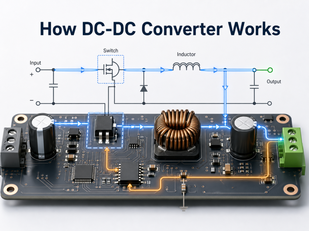
A DC-DC converter is a power circuit that converts one DC voltage level into another DC voltage level. It may step voltage down, step voltage up, or do both depending on the topology. In most modern electronics, the practical job is not just “changing voltage”; it is delivering a stable rail efficiently while the input source, load current, temperature and PCB layout all change.
The core working principle is energy transfer by high-speed switching. A switch, usually a MOSFET inside or beside a controller IC, rapidly connects and disconnects the input. An inductor and capacitor store and smooth energy. A feedback loop measures the output voltage and adjusts the switch duty cycle so the output stays near the target value.
For design and sourcing, do not select a DC-DC converter by output voltage alone. A usable choice must match input range, output current, topology, switching frequency, inductor rating, thermal limits, ripple/noise tolerance, EMI constraints, package and lifecycle. If your main question is topology choice, compare the tradeoffs in Buck vs Boost Converter: What Is the Difference? before sending the full power-rail requirements through Send Inquiry.
Quick Answer: What Does a DC-DC Converter Do?
| Question | Practical Answer |
|---|---|
| What is a DC-DC converter? | A circuit or module that converts DC input voltage to a different regulated DC output voltage. |
| How does it work? | It switches current through energy-storage components, then filters and regulates the output through feedback control. |
| What are the main types? | Buck, boost, buck-boost, inverting, flyback, SEPIC and isolated module topologies. |
| Why use one instead of a linear regulator? | Higher efficiency when voltage drop or load current is large, with less wasted heat. |
| What is the main risk? | Wrong topology, current limit, inductor saturation, poor layout, EMI, thermal overload or unstable output capacitors. |
The Basic Working Principle
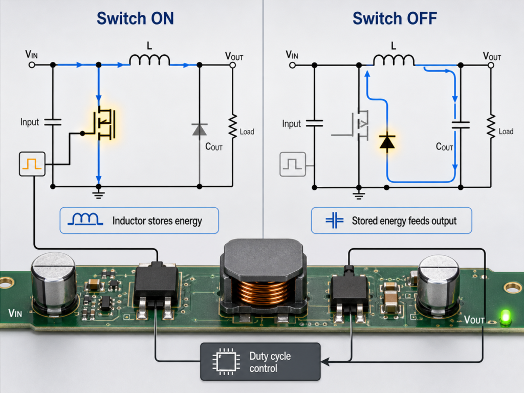
A switching DC-DC converter works in cycles:
- The switch turns on and routes energy from the input into an inductor or transformer.
- The switch turns off and the stored energy continues flowing to the output through a diode or synchronous MOSFET.
- The output capacitor supplies current between switching pulses and reduces voltage ripple.
- The feedback circuit compares the output voltage with a reference and changes the duty cycle, frequency or pulse pattern.
The key idea is that the inductor resists sudden current change. Instead of burning extra voltage as heat, the converter stores energy magnetically and releases it at the voltage needed by the load. This is why a well-designed switching converter can reach high efficiency, while a linear regulator becomes inefficient when the input-output voltage difference and load current are large.
In simplified terms:
Output power = Input power x efficiency
If a 12 V input powers a 5 V, 2 A rail, the output power is 10 W. At 90% efficiency, the input source must supply about 11.1 W and the converter dissipates about 1.1 W as heat. At 75% efficiency, the converter dissipates about 3.3 W. That difference changes package choice, PCB copper area, enclosure temperature and reliability.
Key Components Inside a DC-DC Converter
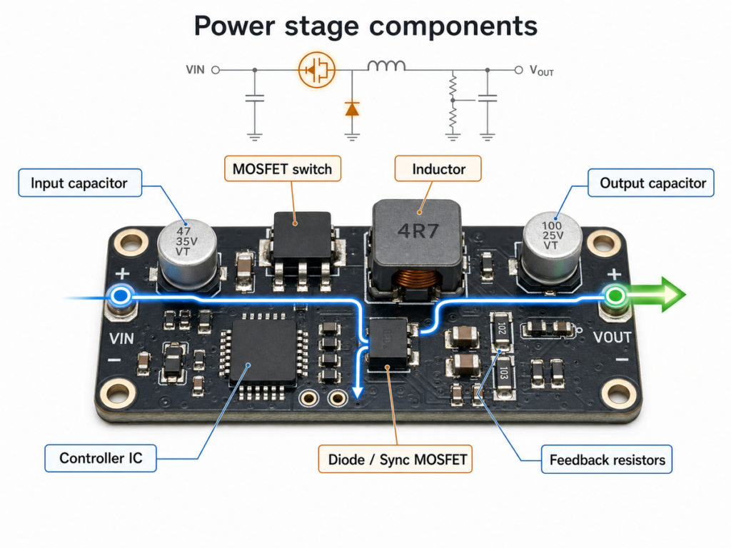
| Component | What It Does | Selection Risk |
|---|---|---|
| Controller or regulator IC | Drives the switching element and regulates the output | Input range, current limit, topology, compensation and package thermal rating must match the design |
| MOSFET switch | Turns current on and off at high frequency | RDS(on), gate charge, voltage rating and switching loss affect heat and efficiency |
| Inductor | Stores energy and controls current ripple | Saturation current, RMS current, DCR and size must match peak current |
| Diode or synchronous MOSFET | Provides a current path when the main switch changes state | Diode forward loss or synchronous timing affects efficiency and heat |
| Output capacitor | Reduces ripple and supports load transients | Capacitance, ESR, voltage rating and DC bias affect stability and ripple |
| Feedback resistors / compensation network | Sets output voltage and loop behavior | Wrong values or layout can cause incorrect voltage or oscillation |
| Input capacitor | Supplies pulsed switch current locally | Poor placement can increase EMI, ringing and input ripple |
For procurement, the regulator IC is only one line item. The converter may fail in production if the inductor current rating, capacitor derating, diode rating or PCB layout does not match the datasheet recommendations. If the passive-component behavior is still unclear, review Resistor, Capacitor and Inductor Explained before locking the power-stage BOM.
How a Buck Converter Steps Voltage Down
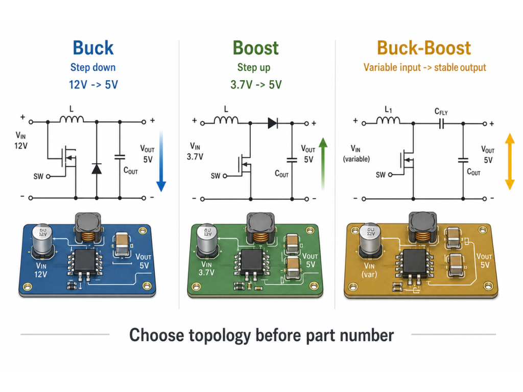
A buck converter converts a higher DC voltage to a lower DC voltage. Typical examples include 24 V to 12 V, 12 V to 5 V, 5 V to 3.3 V and battery pack rails to logic rails.
In a basic asynchronous buck converter:
- When the switch is on, input current flows through the inductor to the load and output capacitor.
- Inductor current ramps upward while energy is stored in the magnetic field.
- When the switch turns off, the inductor keeps current flowing through the diode to the output.
- The output capacitor smooths the pulsed energy into a regulated DC rail.
- The feedback loop adjusts duty cycle to maintain the target output voltage.
In an ideal buck converter, the rough voltage relationship is:
VOUT ~= D x VIN
D is duty cycle, the fraction of each cycle during which the main switch is on. Real converters include losses, minimum on/off time, current limit, diode drop or synchronous MOSFET losses, so the datasheet and design equations matter.
Use a buck converter when the input is always higher than the output, with enough margin for duty-cycle limits and transients.
How a Boost Converter Steps Voltage Up
A boost converter converts a lower DC voltage to a higher DC voltage. Examples include a lithium cell to 5 V, 5 V to 12 V bias supply, LED driver rails and battery-powered circuits that must keep output voltage stable as battery voltage falls.
In a basic boost converter:
- When the switch is on, the inductor charges from the input source.
- During this on-time, the output capacitor supplies the load.
- When the switch turns off, the inductor voltage adds to the input voltage and pushes current through the diode or synchronous MOSFET to the output.
- The feedback loop changes duty cycle to keep the output at the target voltage.
In an ideal continuous-conduction boost converter:
VOUT ~= VIN / (1 - D)
As duty cycle rises, output voltage can rise, but real converters are limited by switch current, inductor saturation, diode or MOSFET stress, thermal dissipation, minimum input voltage and maximum duty cycle. The output current available from a boost converter is usually much lower than the input current. A common mistake is to specify only “5 V output” and ignore the input current needed from the battery or USB rail.
Buck-Boost and Other Topologies
Use a buck-boost converter when the input voltage may be above or below the required output voltage. This is common with batteries because the source voltage changes during discharge. For example, a single-cell lithium battery may need to produce a stable 3.3 V rail while the cell voltage moves above and below 3.3 V.
| Topology | Converts | Typical Use | Key Check |
|---|---|---|---|
| Buck | Higher VIN to lower VOUT | Logic rails, post-regulation, industrial 24 V to 5 V | VIN must stay above VOUT with enough margin |
| Boost | Lower VIN to higher VOUT | Battery to 5 V, LED strings, bias supplies | Switch and inductor current can be high |
| Buck-boost | VIN above or below VOUT | Battery systems, variable input rails | Topology polarity, efficiency and control mode |
| Inverting | Positive input to negative output | Op-amp negative rails, sensor interfaces | Output polarity and ground reference |
| Flyback / isolated DC-DC | Isolated output from DC input | Industrial, telecom, medical or noisy systems | Isolation rating, transformer design, safety spacing |
| SEPIC | Non-inverting buck-boost behavior | Automotive and battery inputs | Coupled/dual inductor and capacitor stress |
The topology choice should be made before selecting a part number. If the input range crosses the desired output voltage, a plain buck or plain boost may not be enough.
What the Feedback Loop Controls
The feedback loop is what makes a converter a regulator rather than a simple voltage-changing circuit. It senses output voltage, compares it with an internal reference and changes switching behavior.
Common control methods include pulse-width modulation, pulse-frequency modulation, current-mode control and constant-on-time control. The exact method affects transient response, light-load efficiency, output ripple and EMI. Many datasheets also specify a stable output capacitor range or compensation network. Ignoring those limits can create output oscillation even if the voltage and current ratings look correct.
For adjustable-output converters, feedback resistors set the output voltage. Use the formula in the specific datasheet. Do not copy values from a different regulator family unless the feedback reference voltage and bias-current assumptions are the same.
Efficiency, Heat and Ripple
Efficiency is not one fixed number. It changes with input voltage, output voltage, load current, switching frequency, MOSFET losses, inductor DCR, diode loss, gate-drive loss and temperature.
| Design Factor | Why It Matters |
|---|---|
| High load current | Increases conduction loss and thermal stress |
| Large conversion ratio | May increase switch current, duty-cycle stress and loss |
| High switching frequency | Reduces inductor/capacitor size but can increase switching loss and EMI |
| Low inductor saturation current | Can cause current limit, overheating or output collapse |
| Poor capacitor derating | Reduces effective capacitance and increases ripple or instability |
| PCB layout | Controls hot loops, EMI, ringing, thermal path and measurement accuracy |
Ripple is the small AC component left on the DC output. Some digital loads tolerate more ripple than analog, RF, sensor or audio rails. If the load is noise-sensitive, check ripple/noise plots, PSRR requirements, post-filtering options and layout guidance. In some designs, a buck converter followed by an LDO is a better architecture than either one alone: the buck reduces most of the voltage efficiently, and the LDO cleans the final rail.
How to Choose a DC-DC Converter
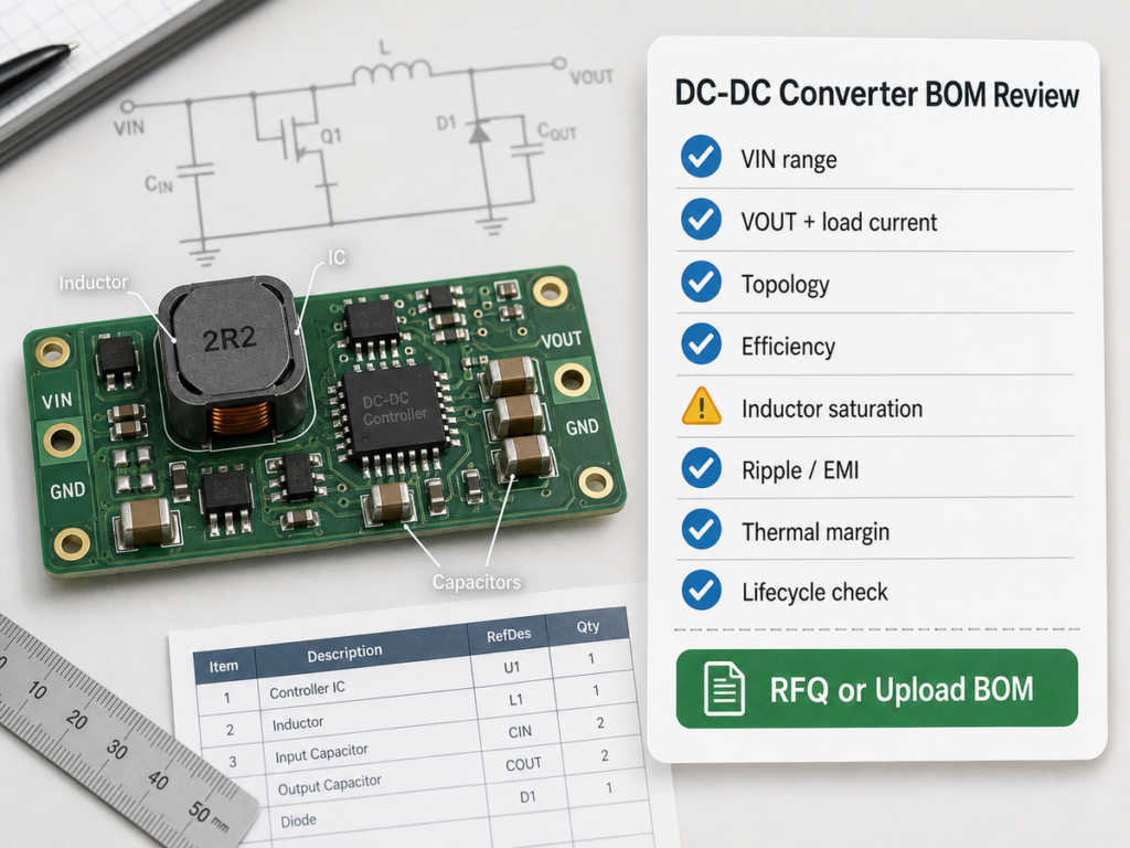
Use this checklist before locking the BOM:
| Step | What to Confirm | Why It Matters |
|---|---|---|
| 1 | VIN(min), VIN(max), surge and startup behavior | Prevents undervoltage dropout, overvoltage stress and startup failure |
| 2 | VOUT, tolerance and rail sequencing | Ensures the load receives the correct regulated rail |
| 3 | Continuous and peak load current | Verifies current limit, inductor rating and thermal margin |
| 4 | Topology: buck, boost, buck-boost, isolated | Avoids selecting a converter that cannot operate across the full input range |
| 5 | Efficiency at actual load points | Predicts heat, battery life and enclosure temperature |
| 6 | Switching frequency and EMI requirements | Affects layout, filter design, inductor size and regulatory testing |
| 7 | Inductor and capacitor recommendations | Prevents saturation, excess ripple and instability |
| 8 | Package and thermal resistance | Confirms the part can dissipate loss on the real PCB |
| 9 | Protection features | OCP, OVP, UVLO, thermal shutdown and soft-start affect fault behavior |
| 10 | Lifecycle, package availability and approved sources | Reduces procurement risk and redesign cost |
For an RFQ, include input range, output voltage, output current, topology preference, package, switching frequency target, isolation need, operating temperature, manufacturer preference and expected annual quantity. For a BOM review, include the inductor and capacitor part numbers too, not only the controller IC.
Common Mistakes
Mistake 1: Choosing by output voltage only. A 5 V converter is not automatically suitable for every 5 V rail. Current limit, efficiency curve, input range, thermal package and transient response may all be wrong.
Mistake 2: Ignoring inductor saturation current. If the inductor saturates, ripple current rises sharply and the converter can overheat, trigger current limit or collapse under load.
Mistake 3: Treating the datasheet efficiency peak as guaranteed. Efficiency curves are measured under specific VIN, VOUT, load and temperature conditions. Your application may run at a less favorable point.
Mistake 4: Using random capacitors. Output capacitor value, ESR, voltage rating, dielectric and DC-bias derating can affect stability and ripple.
Mistake 5: Copying layout loosely. The switch node, input capacitor loop, diode/synchronous MOSFET path and ground return are high-impact layout areas. A poor layout can make a good IC noisy or unreliable.
Mistake 6: Forgetting sourcing constraints. A technically correct part can still be a poor production choice if the package, lifecycle, manufacturer lead time or authorized-channel availability does not match the project.
Applications
DC-DC converters appear wherever a system has one DC source but multiple rail requirements:
| Application | Typical Requirement | Converter Fit |
|---|---|---|
| Battery-powered devices | Keep logic rail stable as battery voltage changes | Buck, boost or buck-boost |
| Industrial control | Convert 24 V field supply to 12 V, 5 V or 3.3 V | Buck converter or isolated module |
| Automotive electronics | Handle wide battery input and transients | Automotive-rated buck, boost or buck-boost |
| LED lighting | Regulate current or voltage for LED strings | Boost, buck or dedicated LED driver |
| Telecom and networking | High-efficiency intermediate rails | Synchronous buck and isolated modules |
| Sensors, RF and analog | Low-noise rail after efficient conversion | Buck plus LDO or low-noise converter |
DC-DC Converter vs Linear Regulator
| Feature | DC-DC Converter | Linear Regulator / LDO |
|---|---|---|
| Efficiency | Usually higher for large voltage drops and higher current | Lower when VIN – VOUT is large |
| Noise/EMI | Switching ripple and EMI require layout/filter care | Generally lower noise and simpler EMI behavior |
| Circuit complexity | Higher: inductor, capacitors, layout, compensation | Lower: usually capacitors and regulator |
| Heat | Lower in many high-current systems | Can be high because excess voltage becomes heat |
| Best use | Efficient power conversion, batteries, high current | Low-noise rails, small voltage drop, low current |
The practical decision is often not either/or. Many designs use a DC-DC converter for efficiency and an LDO linear regulator for final noise cleanup.
Sourcing and BOM Guidance
When buying or replacing a DC-DC converter, classify the requirement by function first:
- Exact replacement: same part number, suffix, package, temperature grade and manufacturer.
- Pin-compatible alternative: same pinout and package, with verified electrical and layout compatibility.
- Parametric alternative: similar voltage/current/topology specs but requires schematic and layout review.
- Functional alternative: same power-rail goal but may need PCB redesign, inductor/capacitor changes or firmware sequencing checks.
For production purchasing, verify lifecycle, authorized supply, packaging type, moisture sensitivity, RoHS/REACH status and the required passive components. Avoid describing a substitute as “fully compatible” unless pinout, package, compensation, enable logic, soft-start, protection behavior, thermal design and BOM passives are all checked. For controller-level sourcing context, the comparison in ADI vs. TI Dual-Phase Buck Controllers shows why part-number selection should include control method, compensation, current capability and surrounding components.
FAQ
What is a DC-DC converter in simple terms?
A DC-DC converter changes one DC voltage into another DC voltage. It can step voltage down, step voltage up, invert polarity or provide isolated rails depending on the topology.
How does a DC-DC converter regulate voltage?
It senses the output voltage through a feedback loop and adjusts the switching duty cycle or pulse pattern. The inductor and capacitor smooth the switched energy into a usable DC output.
What is the difference between a buck and boost converter?
A buck converter steps voltage down. A boost converter steps voltage up. If the input voltage may be both above and below the desired output, use a buck-boost, SEPIC or related topology.
Why does a DC-DC converter need an inductor?
The inductor stores energy when the switch changes state and controls current ripple. Its value, saturation current and resistance strongly affect output current, efficiency, heat and stability.
Why does a DC-DC converter get hot?
Heat comes from MOSFET conduction loss, switching loss, diode loss, inductor resistance, capacitor ESR and control losses. Higher current, poor layout, wrong inductor selection or low efficiency at the actual operating point can make the converter overheat.
Can I replace a DC-DC converter with another part?
Only after checking topology, pinout, package, input range, output voltage, current limit, feedback reference, compensation, inductor/capacitor requirements, enable logic, protection behavior and thermal performance. Many alternatives are parametric, not drop-in replacements.
Request Quote / Upload BOM
If you need a DC-DC converter for a new design or replacement project, prepare the power requirements before sourcing: input voltage range, output voltage, load current, topology, package, operating temperature, efficiency target, ripple/noise limit, isolation requirement and preferred manufacturers.
For a single rail, use Send Inquiry with the target specifications and approved part numbers. For a multi-rail board, include the BOM details so the converter IC, inductor, capacitors, diode or synchronous MOSFET and replacement risk can be reviewed together.
Authoritative Technical References
- Texas Instruments: Basic Calculation of a Buck Converter’s Power Stage – used for buck converter power-stage parameters, duty-cycle relationship and component-selection checks.
- Texas Instruments: Basic Calculation of a Boost Converter’s Power Stage – used for boost converter operating limits, switch current and inductor/capacitor selection context.
- Texas Instruments: Basic Calculations of a 4-Switch Buck-Boost Power Stage – used for buck-boost topology and variable input/output power-stage considerations.
- Analog Devices: Switching Regulator Glossary – used for buck, boost and inverting switching-regulator topology definitions.
- Analog Devices: Buck-Boost Converter – used for the explanation that buck-boost converters regulate when input voltage may be above or below output voltage.
- Monolithic Power Systems: DC/DC Converters Guide – used as manufacturer-backed cross-check for common DC-DC converter types, key parameters and functionality.