
Table of Contents
What Is a Low Dropout Regulator? LDO Basics and Selection Guide
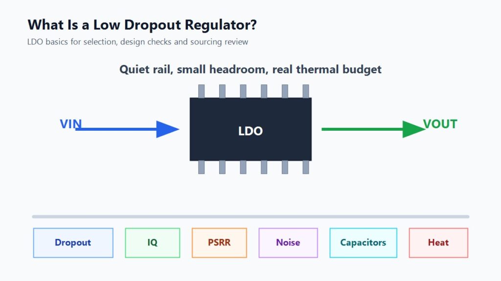
A low dropout regulator, or LDO, is a linear voltage regulator that keeps a stable output voltage when the input voltage is only slightly higher than the output voltage. That required input-to-output difference is called dropout voltage. In practical design, the first LDO check is simple:
VIN(min at the regulator) >= VOUT + VDROP(max at load) + design margin
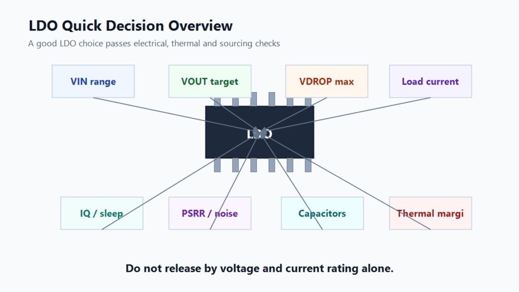
Use an LDO when your circuit needs a compact, low-noise, low-EMI power rail and the voltage drop is small enough that heat remains manageable. Do not choose an LDO only because the output voltage and current rating look correct. Before you release the BOM, check dropout voltage, load current, quiescent current, PSRR, output noise, capacitor stability, package thermal limits and replacement risk.
For sourcing, treat “LDO regulator” as a product category, not a complete purchase description. A usable RFQ should include output voltage, input range, load current, package, dropout requirement, IQ/noise needs, approved manufacturers and any capacitor or pinout constraints.
Quick LDO Decision Table
| Question | Practical Answer |
|---|---|
| What does LDO stand for? | Low dropout regulator. |
| What does an LDO do? | It regulates a lower output voltage from a higher input voltage with a small required input-output headroom. |
| Why use an LDO? | Simple circuit, low output noise, low EMI and small BOM. |
| What is the main design risk? | The extra voltage becomes heat, so thermal margin can limit usable current. |
| What is the main sourcing risk? | Similar LDOs may differ in pinout, package, dropout, capacitor stability, IQ, PSRR and protection behavior. |
| Best fit | Battery rails, microcontroller/sensor rails, RF/analog rails and post-regulation after a switching converter. |
| Weak fit | High-current rails, large VIN-to-VOUT drops and designs where efficiency dominates. |
What Is Dropout Voltage?
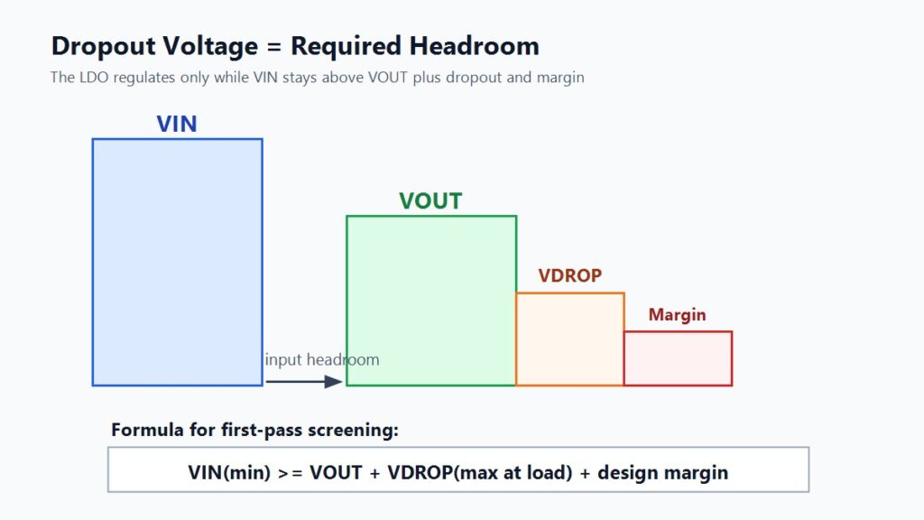
Dropout voltage is the minimum difference between the LDO input voltage and output voltage needed to keep the output in regulation. If the input falls too close to the output, the regulator enters dropout and the output can fall with the input.
For example, a 3.3V output LDO with 300mV dropout needs at least about 3.6V at its input before extra margin. A 3.3V regulator with 1.2V dropout needs about 4.5V before margin. Both may be called LDOs, but they are not equal choices for a low-voltage battery rail.
| Output Rail | Example Dropout | Minimum Input Before Margin | Selection Meaning |
|---|---|---|---|
| 1.8V | 150mV | 1.95V | Useful for low-voltage point-of-load rails if current and noise fit. |
| 3.3V | 300mV | 3.6V | Practical for a rail that remains above 3.6V under load. |
| 3.3V | 1.2V | 4.5V | May work from a 5V rail, but margin can be tight at high load. |
| 5V | 500mV | 5.5V | Requires a source that stays comfortably above 5V. |
The datasheet condition matters. A typical dropout number at light load is not a safe release criterion for a production design. Use the maximum dropout value at your real load current and temperature, then add margin for cable loss, connector drop, battery discharge, input ripple and transient load changes.
How Does an LDO Work?
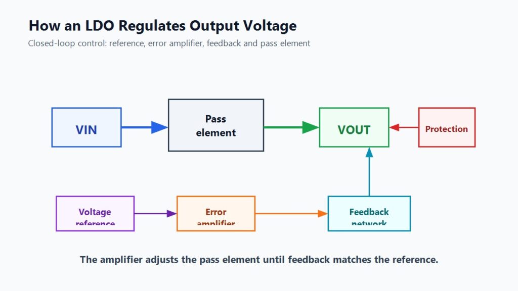
A typical LDO uses a closed control loop. Its internal blocks usually include a voltage reference, an error amplifier, a feedback network, a pass element and protection circuits.
| LDO Block | What It Does | Why It Matters |
|---|---|---|
| Voltage reference | Provides a stable internal comparison voltage. | Output accuracy depends partly on this reference. |
| Error amplifier | Compares feedback voltage with the reference. | Controls regulation and transient response. |
| Feedback network | Samples the output voltage. | Sets or monitors the output voltage. |
| Pass element | Controls current from input to output. | Strongly affects dropout, IQ, heat and stability. |
| Protection circuits | Add current limit, thermal shutdown, UVLO, OVLO or reverse-current behavior depending on the part. | Fault behavior differs between LDOs. |
When the output voltage drops, the feedback voltage drops. The error amplifier reacts by driving the pass element to supply more current. When the output rises, the amplifier reduces pass-element drive. This keeps the output near the target voltage while the regulator has enough input voltage, enough current capacity and enough thermal margin.
Different LDO architectures use different pass devices, such as PMOS, PNP or NMOS structures. This is why two LDOs with the same nominal voltage and current can still differ in dropout voltage, ground current, capacitor requirements and transient behavior.
LDO vs Standard Linear Regulator
An LDO is a type of linear regulator. The difference is that an LDO is designed to regulate with a smaller input-to-output voltage difference than many older standard linear regulators.
| Feature | LDO Regulator | Standard Linear Regulator |
|---|---|---|
| Regulator family | Linear | Linear |
| Dropout/headroom | Lower | Usually higher |
| External components | Usually few | Usually few |
| Output ripple/noise | Low in many designs | Low in many designs |
| EMI | Low | Low |
| Efficiency | Best when VIN is close to VOUT | Poor when large headroom is needed |
| Main limitation | Heat and stability still need checking | Heat and headroom need checking |
Both regulator types dissipate unused voltage as heat. A low dropout rating helps when the input is close to the output, but it does not make the regulator a high-efficiency converter when VIN is far above VOUT.
LDO vs Buck Converter
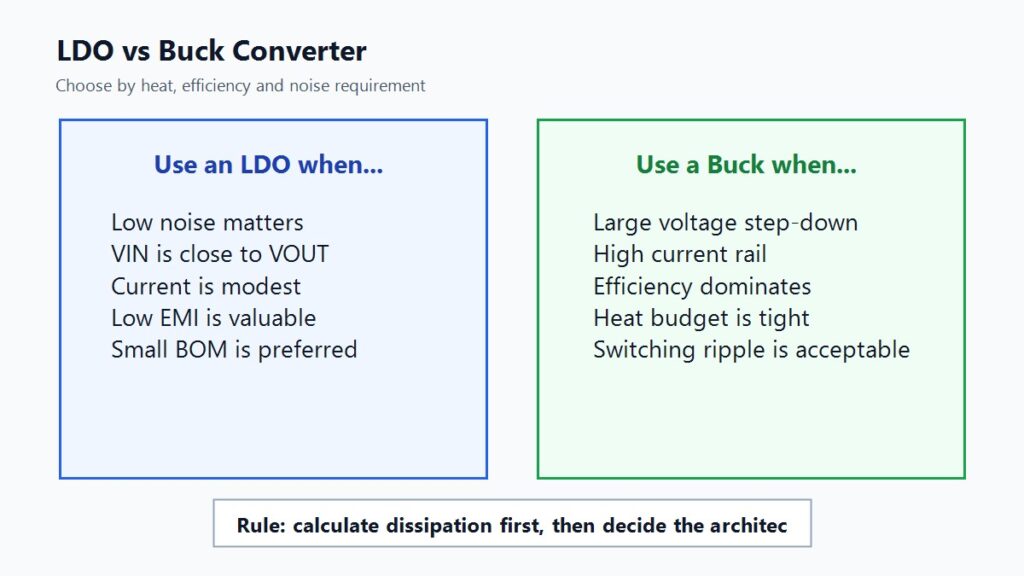
A buck converter is a switching regulator. It is usually the better choice when a design needs high efficiency, high current or a large voltage step down. The tradeoff is more parts, an inductor, switching ripple, layout sensitivity and EMI control.
An LDO is usually the better starting point when the design needs simplicity, low noise, low EMI and modest current, and when VIN is close enough to VOUT.
| Design Case | Better Starting Point | Reason |
|---|---|---|
| 5V to 3.3V at low or moderate current | LDO if thermal margin is acceptable | Simple, quiet and compact. |
| 12V to 3.3V at hundreds of mA | Buck converter | LDO heat is likely excessive. |
| RF, ADC, DAC or audio rail | Low-noise LDO | Noise and PSRR can matter more than efficiency. |
| Battery device with sleep mode | Low-IQ LDO or buck, depending on load | IQ and dropout over the discharge curve are critical. |
| Main digital core rail at high current | Buck converter | Efficiency and heat dominate. |
| Buck output feeding sensitive analog load | Buck plus LDO | Buck handles conversion efficiency; LDO cleans the local rail. |
The common mistake is treating the choice as “LDO good” or “buck good.” It is a power-budget decision. Calculate dissipation, define the noise requirement and then choose the regulator architecture.
Key LDO Selection Parameters
Output Voltage
LDOs may be fixed-output or adjustable-output devices. A fixed LDO might provide 1.8V, 2.5V, 3.3V or 5V without external feedback resistors. An adjustable LDO uses external resistors to set the output voltage.
For selection, output voltage alone is not enough. Verify tolerance across input voltage, load current and temperature. A “3.3V LDO” should be checked against the system rail tolerance, not only its nominal marking.
Input Voltage Range
The input voltage must stay within the device operating range and above the dropout requirement. In a battery design, use the minimum battery voltage under load, not only the fully charged voltage. In a distributed 5V system, include cable, connector and trace losses at peak current.
Dropout Voltage
Dropout voltage decides whether the LDO can regulate when VIN approaches VOUT. Always check the dropout condition in the datasheet: output current, temperature and whether the value is typical or maximum.
Output Current and Current Limit
The output current rating is not a promise that the part can supply that current continuously on your board. It must be checked with power dissipation, package thermal resistance, copper area and ambient temperature. Current-limit behavior also varies, so do not treat the current limit as the intended operating current.
Quiescent Current
Quiescent current, or IQ, is the current consumed by the regulator itself. It matters in standby and battery-powered products. A device with excellent output current capability may still be a poor choice for an always-on sensor rail if its IQ is too high for the sleep budget.
PSRR and Output Noise
PSRR describes how well the LDO rejects input ripple and noise. Output noise is noise generated by the regulator itself. These specifications matter for RF modules, precision sensors, ADCs, DACs, audio circuits and oscillator rails.
Check PSRR at the frequency that matters. A regulator may have strong low-frequency PSRR but weaker rejection near a switching regulator frequency. Layout and capacitor choice also affect the real result.
Capacitor Value, ESR and Placement
Most LDOs need input and output capacitors. The exact capacitance, ESR range, dielectric type and placement rules depend on the specific LDO. Older devices may require a certain ESR range, while many newer devices are stable with ceramic capacitors under stated conditions.
Do not copy capacitor values from a different board or a different LDO family. Verify the exact datasheet and remember that MLCC effective capacitance can fall with DC bias, temperature and package size.
Package and Thermal Resistance
Package choice controls how much heat can leave the die. A small SOT-23 package is convenient for low-current rails, but it may not dissipate enough heat for a larger load. SOT-223, DFN, QFN or TO-252-style packages can offer better thermal paths when the PCB provides enough copper and vias.
Use the thermal equation early:
TJ = TA + PD x RthetaJA(effective)
If the calculated junction temperature is too high, reduce input voltage, reduce current, choose a better package, improve copper area or use a switching converter before the LDO.
Power Dissipation: The Check That Prevents Many LDO Failures
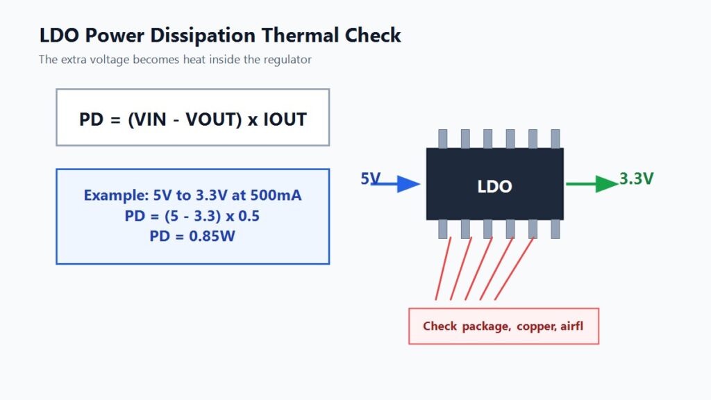
LDO heat is usually estimated with:
PD = (VIN - VOUT) x IOUT
For a more detailed calculation, include regulator ground current or quiescent-current effects according to the datasheet. For first-pass screening, the input-output voltage difference and load current usually reveal the main problem.
Example:
5V to 3.3V at 500mA:
PD = (5V - 3.3V) x 0.5A = 0.85W
That 0.85W may be acceptable on one board and unacceptable on another. The answer depends on package, copper, airflow, ambient temperature and nearby heat sources. At 1A, the same conversion becomes 1.7W before considering other losses, which is a serious thermal check for many compact layouts
Where LDO Regulators Are Commonly Used
| Application | Why an LDO Fits | What to Check Before Release |
|---|---|---|
| Battery-powered devices | Low dropout can extend the usable input range. | Dropout across discharge curve, IQ and shutdown current. |
| MCU and sensor rails | Simple circuit and low BOM count. | Startup current, transient load and capacitor placement. |
| RF modules | Low-noise local supply can improve system performance. | PSRR and noise at relevant frequencies. |
| ADC, DAC and audio circuits | Cleaner rail can protect signal quality. | Output noise, grounding and load transient behavior. |
| Post-regulation after buck | Reduces ripple and local rail variation. | LDO dropout, heat and high-frequency bypassing. |
| Industrial control boards | Local stable rails with protection features. | Temperature range, input transients and fault behavior. |
If the application is noise-sensitive, an LDO can be a strong fit. If the application is high-current and efficiency-sensitive, a buck converter should usually be evaluated first.
Common Mistakes When Selecting an LDO
Mistake 1: Using Typical Dropout as the Design Limit
Typical dropout is useful for comparison, but production designs should be checked with maximum dropout at the required load and temperature. If the input rail has ripple, cable loss or battery droop, add margin.
Mistake 2: Trusting the Current Rating Without Thermal Math
A 1A LDO is not automatically a 1A solution on every PCB. The usable current may be limited by package thermal resistance and board copper long before the electrical current limit is reached.
Mistake 3: Ignoring Quiescent Current
In a battery device, IQ can dominate sleep-mode power. A low dropout voltage does not automatically mean low standby current.
Mistake 4: Copying Capacitors From Another Design
Capacitor value, ESR and placement are part of LDO stability. A capacitor network that works for one LDO may be wrong for another.
Mistake 5: Treating Package Similarity as Replacement Approval
Two LDOs in similar packages may have different pinouts, tab connections, dropout, IQ, capacitor requirements, thermal behavior and protection features. Replacement must be verified by exact part number and datasheet.
LDO Sourcing and Replacement Checklist
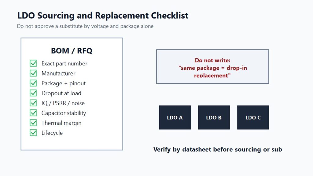
Use this checklist before requesting pricing, approving a substitute or releasing a BOM.
| Check Item | Why It Matters |
|---|---|
| Exact part number | Family name alone may not define voltage, package, tolerance or ordering code. |
| Manufacturer | Generic markings and second-source parts can have different datasheet limits. |
| Output voltage | Fixed and adjustable versions may share similar family names. |
| Input voltage range | Must cover normal operation, startup and fault conditions. |
| Dropout at load | Determines whether the output stays regulated at minimum input. |
| Output current | Must be reviewed with package and thermal conditions. |
| Quiescent current | Critical for standby and battery life. |
| PSRR and output noise | Critical for RF, analog, ADC, DAC and audio rails. |
| Capacitor requirement | Stability depends on value, ESR, dielectric and placement. |
| Package, pinout and tab | Prevents board assembly and electrical mismatch. |
| Protection features | Current limit, thermal shutdown, UVLO/OVLO and reverse-current behavior vary. |
| Lifecycle and availability | Dynamic information must be verified before production sourcing. |
For a clear quotation, provide the desired output voltage, input range, load current, package, manufacturer preference, required IQ/noise level, capacitor constraints and approved substitutions. For multi-line projects, Submit your LDO BOM so sourcing and replacement risks can be reviewed together.
How to Choose an LDO Regulator
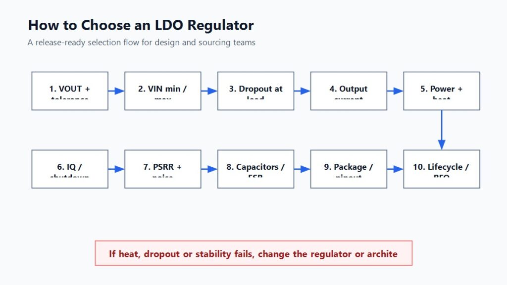
Use this workflow:
- Define the output voltage and tolerance.
- Define maximum, typical and sleep-mode load current.
- Find the minimum input voltage at the LDO pins.
- Check maximum dropout at the real current and temperature.
- Calculate
PD = (VIN - VOUT) x IOUT. - Estimate junction temperature using package and board thermal data.
- Check IQ and shutdown current for battery life.
- Check PSRR and noise for sensitive loads.
- Verify input/output capacitors and ESR requirements.
- Confirm package, pinout, protection and lifecycle before sourcing.
If any step fails, do not force the LDO into the design. Choose a lower-dropout or lower-IQ device, improve thermal layout, reduce input voltage, add a buck converter, or move to a different power architecture.
Author's Viewpoint
The most useful way to think about an LDO is not “simple regulator” but “quiet regulator with a heat budget.” It is often the right part when the voltage drop is small, the load current is moderate and the circuit benefits from low noise. It becomes the wrong part when it is used to burn a large voltage difference at high current.
For engineering teams, the safest habit is to calculate dropout and dissipation before choosing the package. For procurement teams, the safest habit is to ask for the full part number and datasheet-backed replacement review, not just “same voltage, same package.”
If you already know the target rail and load, browse LDO voltage regulators by voltage, current, package, IQ and noise requirements. If the design has multiple power-management parts or substitution constraints, use Request Quote / Upload BOM and include the operating conditions.
FAQ
What is a low dropout regulator?
A low dropout regulator is a linear voltage regulator that maintains a stable output voltage when the input voltage is only slightly higher than the output voltage. That required difference is called dropout voltage.
What does dropout voltage mean in an LDO?
Dropout voltage is the minimum input-to-output voltage difference needed for the regulator to stay in regulation. If input voltage falls below that requirement, output voltage can drop.
When should I use an LDO instead of a buck converter?
Use an LDO when current is modest, the input voltage is close to the output voltage, low noise matters and the thermal calculation is acceptable. Use a buck converter when efficiency, high current or a large voltage step-down dominates.
Why does an LDO regulator get hot?
An LDO gets hot because it dissipates the difference between input voltage and output voltage as heat. The basic estimate is PD = (VIN - VOUT) x IOUT.
Does an LDO need input and output capacitors?
Most LDO circuits need input and output capacitors. The required value, ESR, dielectric and placement depend on the exact part number, so follow the selected datasheet instead of copying another design.
Request Quote / Upload BOM
When sourcing LDO regulators, send the full part number if available. If the exact part is not fixed, send the required output voltage, input range, load current, package, dropout limit, IQ/noise requirement, capacitor constraints and target application.
For project sourcing, alternatives or multi-line power-management BOMs, submit the BOM through:
External References
Toshiba, “What is an LDO regulator?”: https://toshiba.semicon-storage.com/ap-en/semiconductor/knowledge/faq/linear_low-dropout-voltage/low-dropout-voltage-regulators.html
Toshiba, “Basics of Low-Dropout (LDO) Regulator ICs”: https://toshiba.semicon-storage.com/info/docget.jsp?did=13766
Toshiba, “Advantages and disadvantages of linear regulators and switching regulators”: https://toshiba.semicon-storage.com/ap-en/semiconductor/knowledge/faq/linear_low-dropout-voltage/linear-regulator-vs-switching-regulator.html
Analog Devices, “How to Successfully Apply Low-Dropout Regulators”: https://www.analog.com/en/resources/analog-dialogue/articles/how-to-successfully-apply-low-dropout-regulators.html
Analog Devices, “Understand Low-Dropout Regulator (LDO) Concepts to Achieve Optimal Designs”: https://www.analog.com/en/resources/analog-dialogue/articles/understand-ldo-concepts.html
Microchip AN6030, “LDO Basics – Parameter Definitions, Measurements and Calculations”: https://ww1.microchip.com/downloads/aemDocuments/documents/APID/ApplicationNotes/ApplicationNotes/AN6030-LDO-Basics-Parameter-Definitions-Measurements-and-Calculations-DS00006030.pdf
Microchip AN7162, “A Practical Guide to LDO Selection”: https://ww1.microchip.com/downloads/aemDocuments/documents/APID/ApplicationNotes/ApplicationNotes/00007162A.pdf
Texas Instruments, “Learn the basics of linear and low drop-out regulators (LDOs)”: https://www.ti.com/video/series/learn-the-basics-of-linear-and-low-drop-out-regulators-ldos.html