
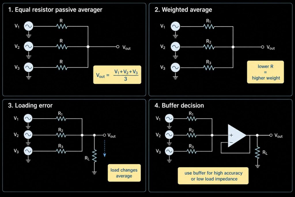
A passive averager is a resistor network that combines two or more voltage inputs into one output node. If all input resistors are equal and the load does not disturb the node, the output voltage is the average of the input voltages. For example, three equal resistors connected to 1 V, 2 V and 3 V will give about 2 V at the common node.
This is useful for simple analog checks, sensor combining, reference trimming and learning circuits. It is also easy to misuse. A passive averager has no active isolation, so source impedance, resistor tolerance and the load connected to the output can change the result. If the average voltage must be accurate, or if the next stage draws current, you may need an op amp voltage follower or a full op amp summing or averaging amplifier.
For op amp IC sourcing, see operational amplifiers. For a true summing amplifier topic, use the separate summing amplifier guide. This page explains the passive averager and when it should hand off to those active circuits.
Quick Answer
| Question | Practical answer |
|---|---|
| What is a passive averager? | A resistor network that creates one node voltage from several input voltages. |
| When is it a true average? | When the input resistors are equal and source/load errors are small. |
| What happens with unequal resistors? | The circuit becomes a weighted averager. Lower resistance gives that input more influence. |
| Main weakness | The output node is not isolated, so a low-impedance load can pull the voltage away from the expected average. |
| When to buffer | Use a voltage follower when the next stage input impedance is not much higher than the averager output impedance, or when accuracy matters. |
| When to use an op amp summing amplifier | Use it when you need gain, controlled weights, signal isolation between inputs, inversion, offset addition or a low-impedance output. |
| Buyer check | Verify resistor tolerance, op amp input bias current, common-mode range, output swing, package, lifecycle and BOM availability before release. |
How a Passive Averager Works
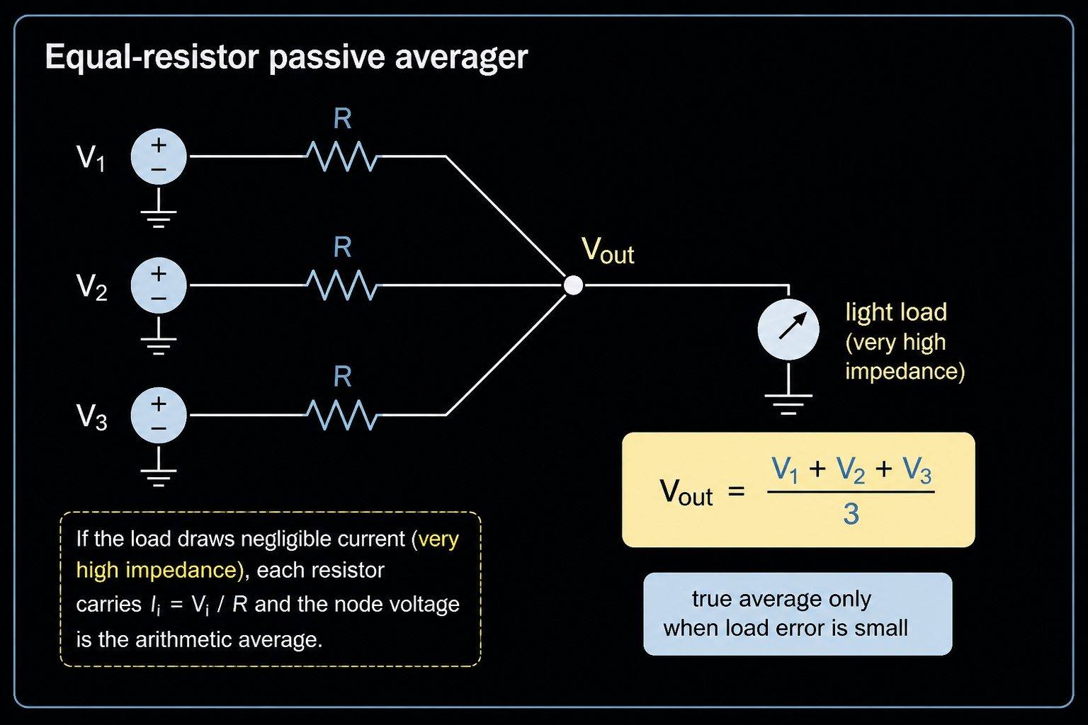
A basic passive averager connects each input voltage to one common output node through a resistor. The output is taken from that node.
For equal resistors:
Vout = (V1 + V2 + V3 + ... + Vn) / n
The circuit works because the currents into and out of the node must balance. If the same resistor value is used for every input, each input has the same effect on the node voltage.
For two equal resistors:
Vout = (V1 + V2) / 2
For four equal resistors:
Vout = (V1 + V2 + V3 + V4) / 4
This simple formula is only the ideal case. It assumes the input sources are stiff voltage sources, the resistors are matched, and the connected load does not pull current from the output node.
Equal Resistors vs Weighted Average
If the resistors are not equal, the output is not the plain arithmetic average. It becomes a weighted average. The input with the lower resistor can push more current into the node, so it has more influence.
For a general resistor network, the node voltage follows a conductance-weighted result:
Vout = (V1/R1 + V2/R2 + V3/R3 + ... + Vn/Rn) / (1/R1 + 1/R2 + 1/R3 + ... + 1/Rn)
This is useful when you want one input to count more than another. It is a mistake when you expected a true average but used mixed resistor values from the BOM.
| Design choice | Result | Procurement note |
|---|---|---|
| All input resistors equal | Arithmetic average | Match tolerance and temperature coefficient if accuracy matters. |
| One resistor is lower | That input has higher weight | Confirm this is intended, not a substitute-value mistake. |
| One resistor is higher | That input has lower weight | Good for weighted averaging, risky for simple averaging. |
| Resistor array used | Better matching may be possible | Verify package, ratio tolerance and availability before approval. |
Loading Error: The Common Passive Averager Problem
The output node of a passive averager is not a strong voltage source. It has finite output impedance. If the next stage draws current, the output voltage changes.
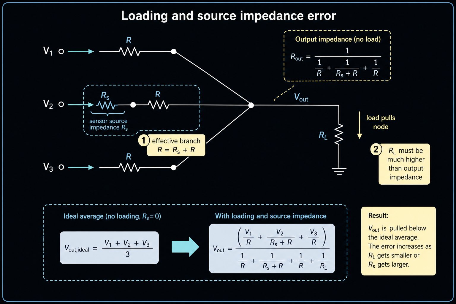
This is the loading effect. It is the main reason a passive averager that works on paper can be wrong on a real PCB.
For an equal-resistor passive averager, the output impedance is roughly the parallel combination of the input resistors, assuming the input voltage sources have low impedance. With three 30 kOhm input resistors, the output impedance is about:
30 kOhm || 30 kOhm || 30 kOhm = 10 kOhm
If this 10 kOhm node drives a 10 kOhm load, the load is not small. It forms another divider and can pull the output far away from the expected average.
A common rule for a rough first check is simple:
Load impedance should be much higher than the averager output impedance.
For many simple circuits, designers want the load impedance to be at least 10 times higher. For precision circuits, even 10 times may not be enough. The final error budget decides.
Source Impedance Also Changes the Average
The input voltage sources are not always ideal. A sensor, divider, DAC output or reference output may have its own source impedance. That impedance is effectively added to the resistor in that branch.
If one input has extra source resistance, that input gets less weight than expected. The circuit may still look like it uses equal resistors, but the real branch resistances are not equal anymore.
| Branch | External averaging resistor | Source impedance | Effective branch resistance |
|---|---|---|---|
| V1 | 10 kOhm | 100 Ohm | 10.1 kOhm |
| V2 | 10 kOhm | 5 kOhm | 15 kOhm |
| V3 | 10 kOhm | 100 Ohm | 10.1 kOhm |
V2 will have less effect on the average because its branch resistance is higher. If V2 is a high-impedance sensor output, this can create a design error and may also disturb the sensor itself.
When to Add an Op Amp Buffer
Use a buffer when the passive averager gives the right voltage but cannot safely drive the next stage. The normal buffer is a voltage follower: the signal goes into the non-inverting input, and the op amp output connects back to the inverting input. The voltage gain is about 1.
The buffer gives the averaging node a high input impedance and gives the next stage a lower output impedance. It does not fix every problem, but it can greatly reduce loading error.
| Situation | Why a buffer helps |
|---|---|
| The next stage input impedance is close to the averager output impedance | The buffer reduces load current drawn from the passive node. |
| The average drives an ADC input | The ADC input may draw dynamic current during sampling. Check the ADC input drive requirements. |
| The node drives a cable, filter or low-value resistor | The passive node is too weak for that load. |
| The source signals must not disturb each other | A better active topology may isolate inputs more cleanly. |
| Accuracy is part of the design goal | Buffer input bias current and offset can be included in the error budget. |
When choosing the op amp, do not check only price and package. Check unity-gain stability, input bias current, input offset voltage, common-mode input range, output swing, output current, capacitive-load behavior, supply voltage, channel count, package and lifecycle.
Buffer Limits You Still Need to Check
A voltage follower is simple, but it is not magic. A real op amp has limits.
| Limit | Why it matters for a passive averager |
|---|---|
| Input bias current | Bias current flows through the averager output impedance and creates voltage error. |
| Input common-mode range | The average voltage must stay inside the valid input range of the op amp. |
| Output swing | The buffered output must reach the required voltage on the selected supply rails. |
| Unity-gain stability | Not every op amp is stable as a voltage follower. |
| Load capacitance | Long traces, cables and ADC inputs can make some op amps ring or oscillate. |
| Noise and offset | High-value resistors and precision averages can make small op amp errors visible. |
For high-impedance networks, input bias current can become a real DC error. Manufacturer data should be checked under the expected temperature range, not only at room temperature.
Passive Averager vs Summing Amplifier
A passive averager and a summing amplifier are related circuits, but they serve different purposes. A passive averager uses only resistors to combine and average signals, while a summing amplifier uses an operational amplifier to provide active summation, gain, buffering, and signal isolation.
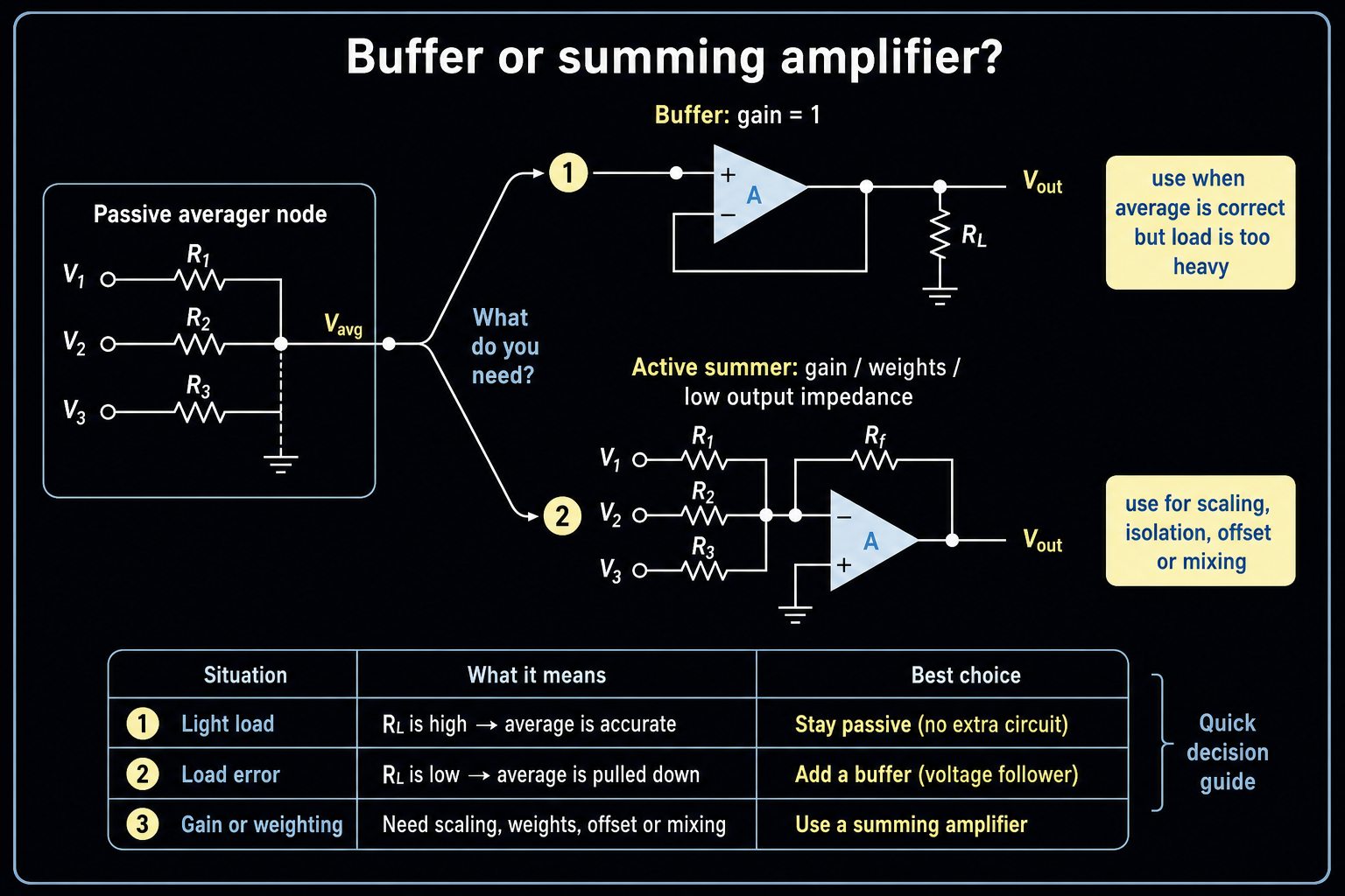
The passive averager is a resistor network. Its main question is: "Can I get the average voltage with only resistors, and what errors will load or source impedance cause?"
The summing amplifier is an op amp circuit. Its main question is: "How do I add, weight, invert, offset or mix multiple inputs with an active circuit?"
| Need | Better choice |
|---|---|
| Simple average with no gain and very light load | Passive averager |
| Weighted average but no active IC allowed | Passive weighted averager, with careful loading checks |
| Average node must drive another circuit | Passive averager plus buffer |
| Inputs must be isolated from each other | Op amp summing or averaging amplifier |
| Output needs gain or controlled scaling | Op amp summing amplifier |
| Output must be low impedance | Op amp buffer or summing amplifier |
| Audio mixing, DAC summing or offset addition | Summing amplifier |
For detailed formulas, op amp adder design, and active signal summation, see our Summing Amplifier guide.
Design Checklist for Engineers
Before using a passive averager in a real design, check these points:
- Are all averaging resistors intentionally equal or intentionally weighted?
- What are the resistor tolerance and temperature coefficient?
- What is the output impedance of the resistor network?
- What load will connect to the output node?
- What is each input source impedance?
- Can one input source back-drive another through the resistor network?
- Does the next stage draw DC current, sampling current or transient current?
- Is the expected error acceptable over temperature?
- If buffered, is the op amp stable at unity gain?
- Does the op amp input/output voltage range fit the supply rails?
If any answer is unclear, move the circuit into simulation and include the exact source impedance, load impedance and op amp input model.
BOM and RFQ Checks
For a simple passive network, procurement still matters. The same schematic can behave differently if resistor values, tolerances or packages change.
| BOM item | Check before release |
|---|---|
| Resistance value | Confirm equal values or intentional weighting. |
| Tolerance | Use tighter tolerance where average accuracy matters. |
| Temperature coefficient | Important when the average must stay stable over temperature. |
| Package | Confirm assembly process, voltage rating and power rating. |
| Resistor array | Check ratio tolerance, pinout and availability. |
| Op amp buffer item | Check before release |
|---|---|
| Supply voltage | Must match the actual single-supply or dual-supply rails. |
| Input bias current | Must be low enough for the network impedance. |
| Input common-mode range | Must include the average node voltage. |
| Output swing and current | Must drive the next stage without clipping or overload. |
| Stability | Must be safe as a voltage follower or in the selected gain. |
| Package and pinout | Must match PCB layout and assembly needs. |
| Lifecycle and compliance | Verify from manufacturer or distributor data before purchase. |
Do not treat stock, price, lead time or compliance as fixed article facts. They change. Submit the exact resistor network, op amp part number, package, quantity and target date through RFQ or BOM review.
FAQ
What is a passive averager circuit?
A passive averager circuit uses resistors to combine multiple input voltages into one output node. With equal resistors and a very light load, the output is the arithmetic average of the inputs.
Why is my passive averager output not the expected average?
The usual reasons are unequal resistor values, resistor tolerance, source impedance, or loading from the next circuit. A low-impedance load can pull current from the output node and change the voltage.
Is a passive averager the same as a summing amplifier?
No. A passive averager is a resistor network with no active gain. A summing amplifier uses an op amp to add or weight signals and can provide gain, isolation and a stronger output.
When should I buffer a passive averager?
Buffer it when the next stage may load the averaging node, when the average drives an ADC input, or when accuracy matters. Choose an op amp with suitable bias current, input range, output swing and unity-gain stability.
Can I use different resistor values in a passive averager?
Yes, but the circuit becomes a weighted averager. That can be useful, but it is not a plain average. Lower resistor values give more weight to their input voltages.
Request Quote / Upload BOM
If your design uses a resistor averaging network, an op amp buffer, or an active summing/averaging amplifier, send the exact BOM for review. Include resistor values and tolerance, source impedance estimates, supply rails, expected signal range, load type, op amp part numbers, package requirements and target quantity.
Use Request Quote for specific parts and quantities. Use Upload BOM when the project has multiple resistor networks, op amp ICs, alternatives or lifecycle checks.
External Sources
- Electronics Tutorials, "Passive Averager Circuit Generates an Average Voltage Output": https://www.electronics-tutorials.ws/opamp/passive-averager.html
- AllAboutCircuits textbook, "Averager and Summer Circuits": https://www.allaboutcircuits.com/textbook/semiconductors/chpt-8/averager-summer-circuits/
- Texas Instruments, "AN-20 An Applications Guide for Op Amps": https://www.ti.com/lit/pdf/snoa621
- Texas Instruments, "Understanding Operational Amplifier Specifications": https://www.ti.com/lit/pdf/sloa011
- Analog Devices, "MT-038: Op Amp Input Bias Current": https://www.analog.com/MT-038