
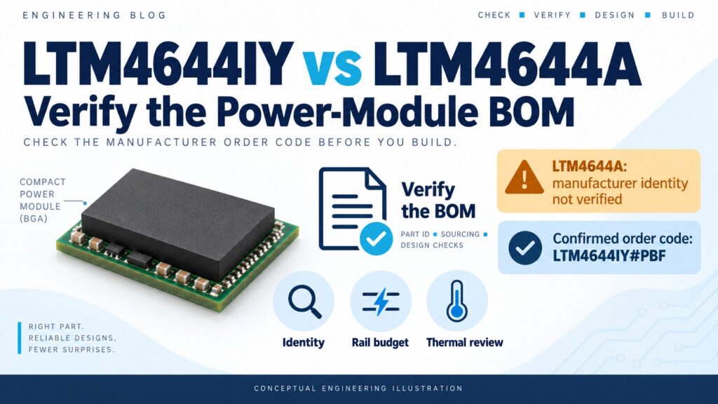
LTM4644IY#PBF is a documented Analog Devices quad-output step-down µModule regulator. LTM4644A has not been verified as a separate manufacturer orderable part in the sources reviewed for this guide. A claimed upgrade or direct replacement therefore needs its own manufacturer evidence before it belongs in a design comparison. Start with the complete order code, then assess the power rails, feedback circuit and thermal operating point. ADI's LTM4644 product catalog.
The useful selection task is to connect a verified component identity to the actual board requirements. This guide explains the listed IY and #PBF codes, the documented LTM4644-1 feedback distinction, and the checks that turn a four-output power module into an approved BOM item.
Start with the complete manufacturer order code
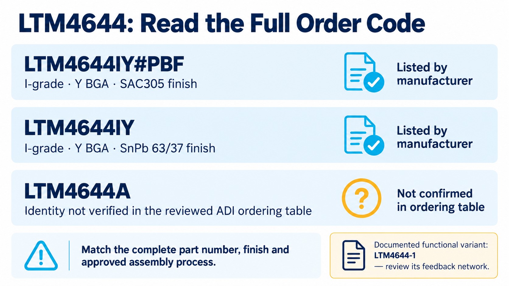
LTM4644IY and LTM4644IY#PBF are both listed order codes, with different ball finishes. The LTM4644/LTM4644-1 ordering table identifies the #PBF version as SAC305 and the unsuffixed IY version as SnPb 63/37. Keep that difference in the BOM and assembly review rather than silently shortening both to “LTM4644IY.”
| Label encountered | What the manufacturer evidence establishes | Design or purchasing action |
|---|---|---|
| LTM4644IY#PBF | Listed I-grade, Y-package BGA order code with SAC305 finish | Match the complete approved BOM entry and assembly process |
| LTM4644IY | Listed I-grade, Y-package BGA order code with SnPb 63/37 finish | Check the required finish instead of dropping the suffix |
| LTM4644-1 | Documented functional variant requiring an external top feedback resistor | Review its specific divider and control circuit |
| LTM4644A | No separate orderable identity established by the reviewed ADI catalog and ordering table | Obtain the exact manufacturer part number and its source document before comparison |
The last row is an evidence boundary, not a claim that no historical or differently documented item could ever use that label. If a supplier proposes it, request the complete manufacturer code and the applicable data sheet. An informal schematic label or an article headline is insufficient to establish voltage accuracy, pin compatibility or a substitution approval. Do not automatically relabel an A entry as LTM4644-1.
Put the verified operating conditions beside the schematic
The ordinary LTM4644 input specification is 4–14 V when SVIN is connected to VIN. The extended 2.375–14 V range requires an external bias arrangement. Review the bias conditions and the intended circuit before using that lower limit.
| Item | Verified LTM4644 information | What to check on the board |
|---|---|---|
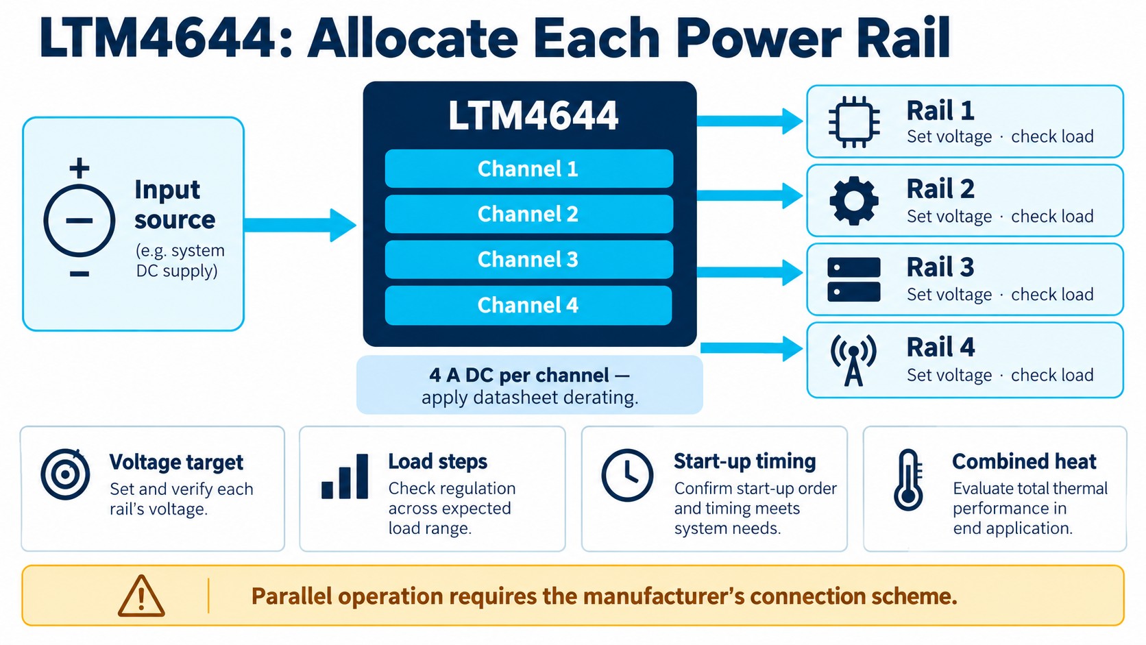
| Channels | Four step-down outputs | Allocate each load and its startup requirements |
| Normal input range | 4–14 V, with SVIN = VIN | Include supply tolerance, ripple and startup behavior |
| Extended input option | Down to 2.375 V with external bias | Follow the bias requirements in the data sheet |
| Adjustable output range | 0.6–5.5 V | Check voltage, duty-cycle and load constraints together |
| Output current | 4 A DC and 5 A peak per channel | Apply the specified operating conditions and thermal derating |
| Package envelope | 77-lead BGA, 9 × 15 × 5.01 mm | Use the current package and land-pattern drawings |
| I-grade temperature | −40°C to +125°C internal operating temperature | Determine allowable ambient conditions from the actual assembly |
Use operating limits and stress limits for their respective purposes. The 15 V input absolute maximum does not make 15 V a normal design operating point. Likewise, the package-height figure should come from the manufacturer's envelope drawing before an enclosure or PCB clearance is released.
Treat regulation figures as specifications with conditions
The manufacturer's feature summary already lists ±1.5% total output voltage regulation for LTM4644. A statement that an unverified A version improves an original ±2% rating has no established basis in these sources.
For a tolerance budget, use the electrical-characteristics conditions and include the external divider, distribution losses and load behavior. The voltage at the module output and the voltage at the consuming IC can differ because of the board's current path. Define where the requirement applies and measure there.
Allocate channels using the actual rail requirements
Make a rail table before selecting independent or parallel operation. For each load, record nominal voltage, allowed deviation, sustained current, transient current, startup order and whether it can be powered while adjacent loads are off. A four-channel rating does not remove those system requirements.
| Rail-review field | Question to answer before assigning a channel |
|---|---|
| Voltage target | Which supply tolerance must the consuming device receive? |
| Current profile | What are the sustained load and the size and speed of load steps? |
| Timing | Must this rail start before, after or alongside another rail? |
| Operating modes | Which combinations of active channels occur in the real product? |
| Thermal case | Which combination produces the most demanding enclosure condition? |
Keep the rail table with the schematic revision. It gives a clear reason for changing a capacitor, divider, operating mode or channel assignment and lets purchasing distinguish an approved part change from a name-only substitution.
The module supports parallel output arrangements for higher-current rails. Follow the manufacturer's current-sharing and connection scheme, including the relevant control and feedback connections. Adding the four channel ratings or joining output nets without reviewing that scheme is not a qualification process.
When comparing options, account for the voltage difference between input and output and the duty-cycle constraints. A configuration that works at one bench operating point still needs assessment across the intended source range and every planned load combination.
Use the documented feedback distinction when reviewing variants
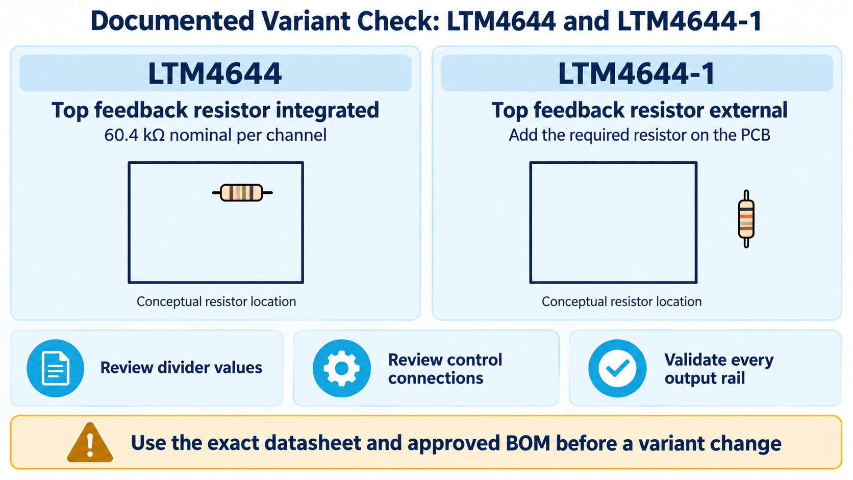
The documented LTM4644 versus LTM4644-1 distinction is the top feedback resistor. LTM4644 integrates a nominal 60.4 kΩ top resistor per channel. LTM4644-1 requires an external top resistor on the PCB. This is a specific circuit difference; it does not establish a performance hierarchy for an unverified A version.
Inspect the implemented divider before approving a variant change. Record which resistors are inside the module and which are populated on the carrier. Then review the feedback equation and resistor selection for the exact part and channel arrangement. Parallel outputs introduce further connection and effective-divider considerations, so avoid carrying a single-channel assumption into a different output array.
The DC2428A evaluation platform provides a documented LTM4644-1 power-management example with an LTC2975 supervisor. That example gives a concrete reason to study the external-divider variant. It does not grant approval to exchange module codes in another board without checking the circuit.
Use the same discipline for RUN, TRACK/SS, PGOOD, operating-mode and clock connections. Compare their actual wiring and intended behavior rather than relying on a statement that package dimensions match. Capture startup and shutdown behavior on the board when a component change affects a rail sequence.
Validate the PCB, thermal environment and load steps together
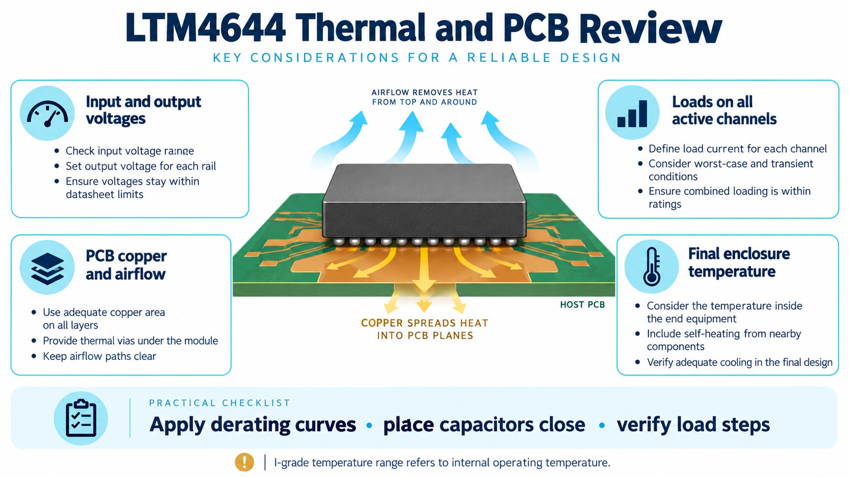
Current capability depends on the operating point and the heat path. Read the data-sheet derating curves using the input voltage, output voltages, active loads and ambient environment relevant to the product. The I-grade internal-temperature range is not an unconditional promise that the assembled board can run at the same ambient temperature under every load.
Review the copper distribution, thermal connections and available airflow alongside the enclosure. Record which channels are active during a thermal test and how each is loaded. Testing one lightly loaded rail provides different evidence from testing the application's most demanding channel combination.
External capacitors remain part of the design even though controllers, power switches and inductors are integrated in the module. Select their effective capacitance and ratings for the actual operating point. Place the input and output networks as directed by the layout guidance, and keep the high-current paths and feedback routing under review.
For load-step testing, define the step amplitude and slew rate, measurement location and operating mode. Keep the test arrangement consistent when comparing board revisions. Ripple and transient results without these details are difficult to use as acceptance criteria.
Use a demo board as a documented starting point
The DC1900A demo manual describes an LTM4644EY board with four configurable rails. It includes setup, transient and thermal examples with stated conditions. The demo's E-grade component and board configuration should be identified when using it to evaluate an I-grade production BOM.
Its quick-start procedure asks for a 4.5–14 V supply preset and checks initial readings within ±2%. Those are instructions for that evaluation procedure. The module's normal operating specification and total-regulation limits still come from its data sheet. Keep the procedure, board result and component specification clearly identified in the test record.
Build a qualification sequence around the approved design: inspect assembly, establish the input and bias arrangement, check no-load startup, add rail loads, apply the intended transients, and evaluate the final thermal configuration. The supplier's published demonstration is useful evidence about that demonstration; the production board needs its own acceptance results.
Turn the verified design into an RFQ-ready BOM
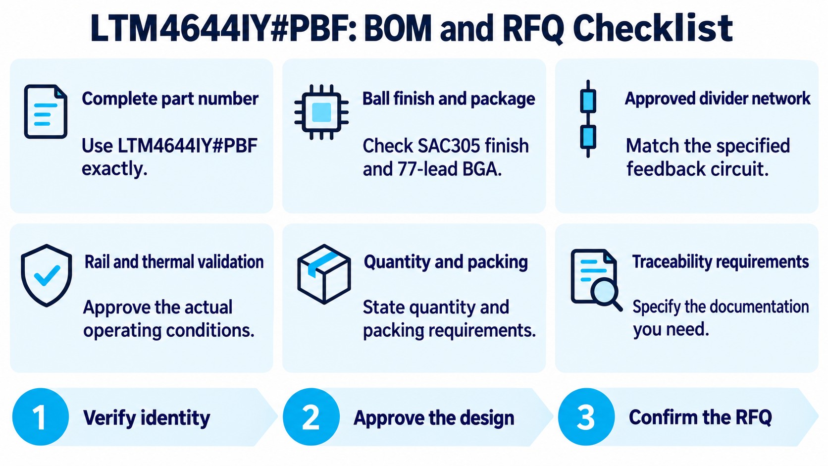
Specify LTM4644IY#PBF when that is the approved order code. Include the finish, package and relevant assembly requirements in the purchasing record. Where an alternative is permitted, attach the engineering approval and the exact accepted code rather than a broad family label.
Before asking for a quotation, prepare:
- The complete manufacturer part number and required quantity.
- Packing and delivery requirements for the purchasing request.
- Any date-code preference, documentation or traceability requirements.
- The approved circuit revision and relevant feedback-network constraints.
- The substitution rules and the engineer responsible for accepting a change.
If an offer uses LTM4644A, pause the part comparison until its manufacturer identity and documentation are supplied. Record the evidence gap rather than filling an A column with assumed current, regulation or package values. This also avoids asking purchasing to source a code whose relationship to the approved circuit has not been established.
Review the LTM4644IY#PBF product record for the verified module specifications and datasheet entry. Send your complete BOM requirements for an RFQ so commercial availability, price and supporting documentation can be confirmed for the actual request.
Frequently asked questions
Is LTM4644A a verified upgrade to LTM4644IY?
The reviewed ADI catalog and LTM4644/LTM4644-1 ordering table did not establish a separate LTM4644A orderable identity. Obtain its complete manufacturer code and applicable data sheet before treating it as an upgrade or replacement.
Are LTM4644IY and LTM4644IY#PBF the same purchasing code?
They are distinct listed order codes. The ordering table identifies SnPb 63/37 for LTM4644IY and SAC305 for LTM4644IY#PBF. Keep the finish and the approved assembly process in the purchasing review.
What is the actual LTM4644 versus LTM4644-1 difference?
LTM4644 integrates the nominal 60.4 kΩ top feedback resistor for each channel. LTM4644-1 requires an external top resistor. Review the complete divider and control circuit before approving a variant change.
Can the four channels be used as a 16 A output?
The manufacturer documents parallel configurations for higher-current outputs. Use the prescribed connections and evaluate operating and thermal limits; the sum of the headline channel ratings alone does not establish a qualified 16 A rail.
Does I-grade allow a +125°C ambient temperature at full load?
The I-grade range refers to internal operating temperature. Allowable ambient conditions depend on the loads, voltages, PCB, cooling and enclosure, and require the applicable derating review and board validation.
Reviewed October 12, 2026 against ADI LTM4644/LTM4644-1 data sheet Rev. G, the manufacturer product catalog and the linked evaluation documentation. Illustrations are conceptual; LTM4644A remains an unverified label in this review.