
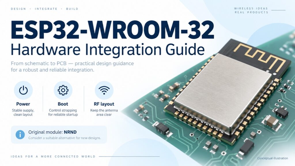
ESP32-WROOM-32 is the original Espressif Wi-Fi and Bluetooth MCU module with an ESP32-D0WDQ6 processor, 4 MB SPI Flash and an on-board PCB antenna. It needs external power and application circuitry. Espressif's current datasheet marks this exact module Not Recommended for New Designs (NRND). For an existing approved design, the useful questions are whether the carrier board starts reliably, the antenna works in the enclosure and the purchased module matches the BOM. Original module datasheet.
This guide follows a hardware review from power input to production purchasing. Keep the original module's identity separate from a development board and from newer ESP32-WROOM variants throughout that review.
What is ESP32-WROOM-32—and what does your carrier board still need?
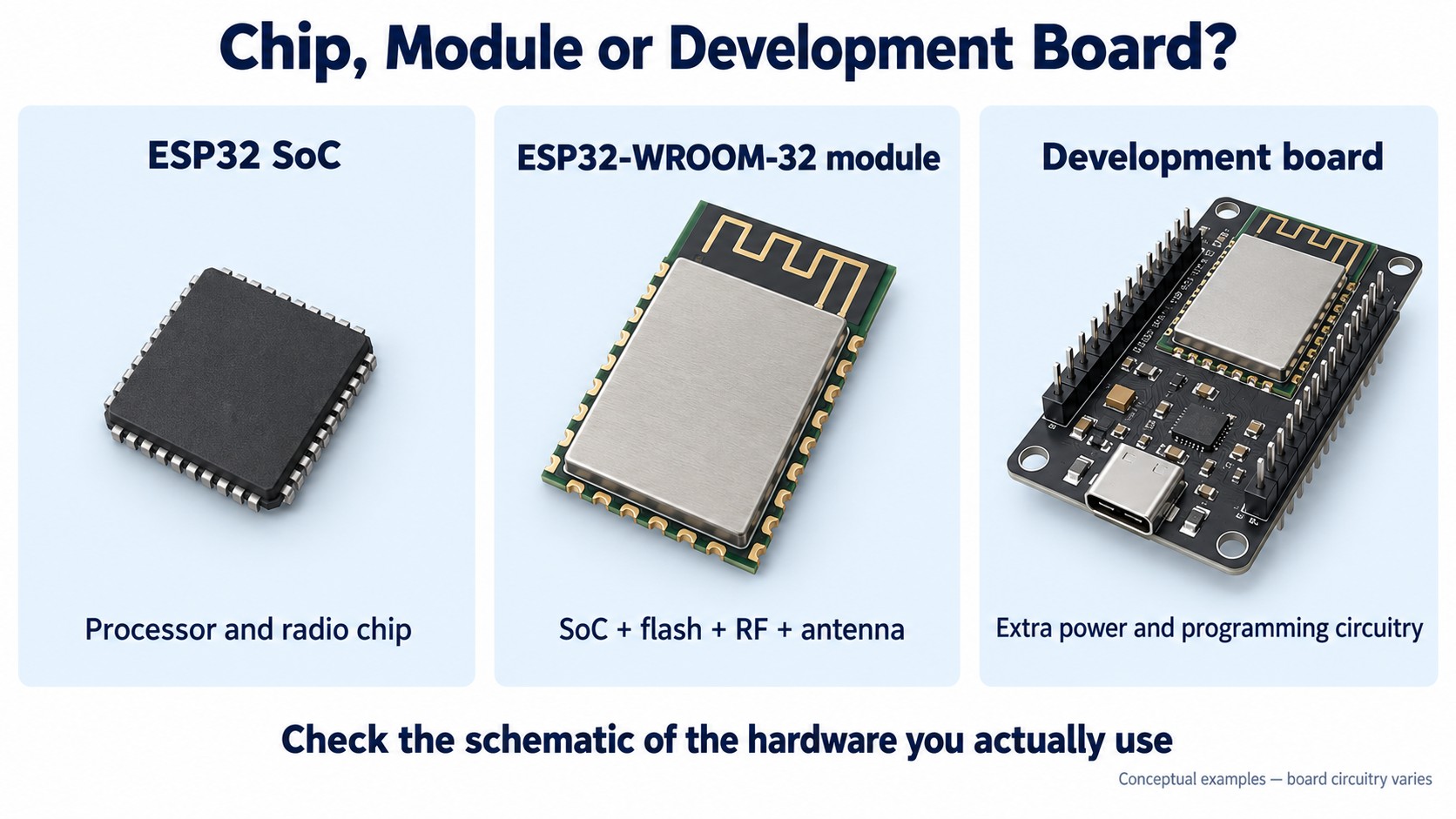
An ESP32 SoC is the processor and radio chip. An ESP32-WROOM-32 module adds Flash, the RF implementation and a PCB antenna. A development board places a module on a larger PCB and may add a regulator, USB-to-UART interface, buttons and connectors. Those extra circuits belong to the board schematic.
This distinction matters when a prototype moves to a custom PCB. A development board that accepts USB power does not establish the bare module's input voltage. Successful automatic programming on that board does not mean a new carrier has the necessary reset circuit. Even an example LED assignment may refer to a particular board rather than the module.
Original-module facts to put beside the schematic
| Item | ESP32-WROOM-32 | Review implication |
|---|---|---|
| Processor | ESP32-D0WDQ6; dual-core Xtensa LX6, up to 240 MHz | Check the firmware target and approved hardware revision |
| Flash | 4 MB SPI Flash | Match image size and partition layout |
| Radio | 2.4 GHz Wi-Fi 802.11b/g/n; Bluetooth 4.2 BR/EDR and LE | Define required protocols before selecting a module |
| Supply input | 3.0–3.6 V; 3.3 V nominal | Verify voltage at the module under load |
| Antenna | On-board PCB antenna | Reserve its placement and clearance early |
| Nominal module size | 18 × 25.5 × 3.1 mm | Use the actual land-pattern drawing for PCB release |
| Operating ambient temperature | −40°C to +85°C | Assess the environment immediately outside the module |
| Lifecycle | NRND | Review existing-design support and new-design options separately |
These values refer to the original part, not every product whose label begins with “ESP32.” Dimensions are nominal; tolerances, pads and the ground connection require the manufacturer's drawings.
Supply the module correctly before debugging firmware
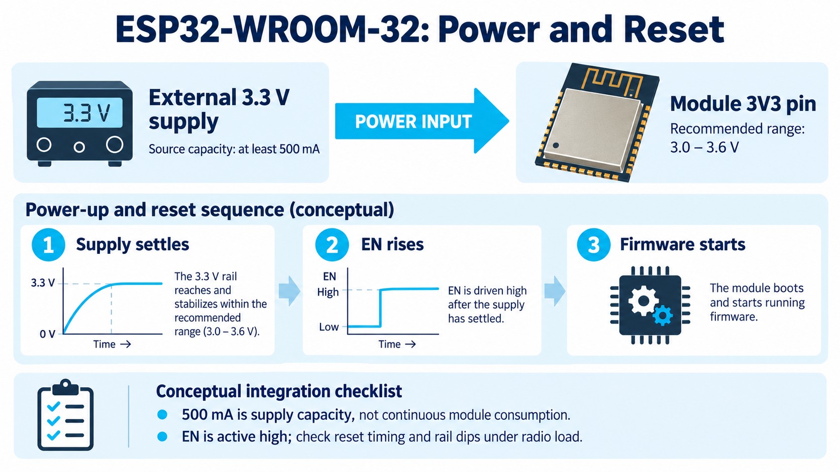
The module's 3V3 pin is a power input. Apply a suitable external regulated rail; a bare ESP32-WROOM-32 is not a 5 V USB-powered development board. The module datasheet specifies an external supply capable of delivering at least 0.5 A. That is a supply-design requirement, not a statement that the module continuously draws 500 mA.
Review the complete current path: source, regulator, connectors, copper and local decoupling. Include other loads sharing that rail. A regulator's headline current rating does not establish that voltage stays within range during the application's radio activity or a shared-load transient.
A practical bench check is to probe 3V3 close to the module while the intended firmware connects and transmits. Record minimum voltage, startup behavior and any resets. Repeat with the intended input source and wiring. A short laboratory supply lead and an unloaded carrier can conceal problems in the eventual assembly. These are engineering validation steps rather than a guarantee of performance for an unspecified board.
Give EN a defined startup sequence
EN enables the module when high. Establish a defined level and release it after the supply is stable. Espressif discusses an external RC reset arrangement in its ESP32 schematic checklist. Treat the recommended circuit as a starting point, then check the actual power ramp, reset pulse and any USB-to-UART control signals.
For a slow supply ramp, an RC network alone may not provide the required reset behavior; review the supply-monitoring approach. During bring-up, observing the rail and EN together helps separate a power sequence problem from a firmware failure.
Plan GPIO around reset, Flash and input-only restrictions
A signal that works after startup may still prevent the module from booting. Make a GPIO allocation sheet that records the function during reset as well as the application function. Read the original module's pin table alongside the ESP-IDF GPIO documentation; a chip-level list alone does not establish which signals a specific module exposes or reserves.
| GPIO group | Original-module constraint | Carrier-board check |
|---|---|---|
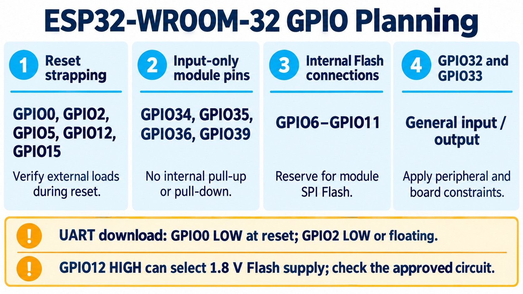
| GPIO0, 2, 5, 12 and 15 | Strapping states are sampled around reset | Inspect pull resistors and external devices active at startup |
| GPIO34, 35, 36 and 39 | Exposed input-only signals; no internal pull-up or pull-down | Provide external bias when needed; do not assign output functions |
| GPIO6–11 | Connected to the module's SPI Flash | Reserve them for Flash rather than general application wiring |
| GPIO32 and 33 | Support input and output | Check the selected peripheral and any shared board connections |
| UART0 TX/RX | Commonly used for flashing and boot diagnostics | Preserve programming access or document the approved alternative |
The distinction between input-only signals and general I/O is important for sensor interfaces. GPIO32 and GPIO33 are not part of an all-input-only “GPIO32–39” group. Likewise, do not assume every chip GPIO is a freely available module pin.
Check download-mode conditions deliberately
For UART download, hold GPIO0 low during reset and keep GPIO2 low or floating. With GPIO0 high, the normal path executes the Flash program. GPIO12 can select the Flash-supply voltage; pulling it high can select 1.8 V and cause trouble when the Flash needs 3.3 V. GPIO15 affects ROM boot-message output rather than serving as the main GPIO0-style download selector. See Espressif's boot-mode selection guide.
Inspect connected sensors, level translators and other controllers in their own reset states. An application may leave a pin correctly configured after initialization while an external circuit drives an unsuitable level before initialization. Capture the boot log and electrical state before changing firmware at random.
Place the PCB antenna before routing the rest of the board
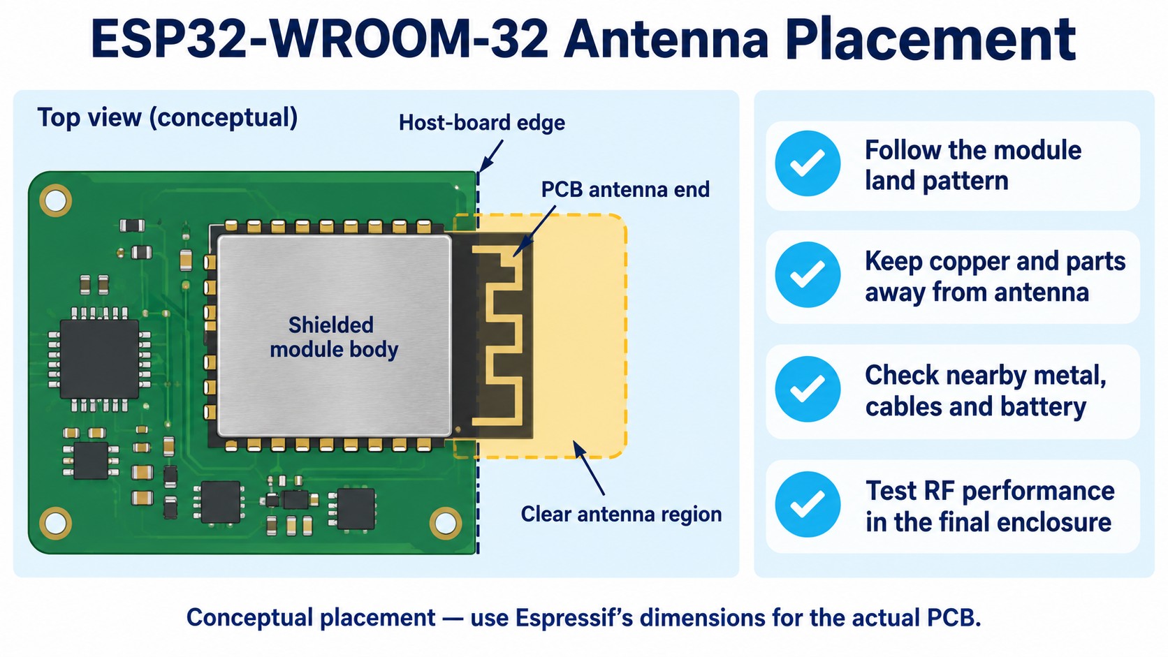
The antenna region is part of the mechanical design. The module datasheet points to Espressif's module PCB-layout guidance. Use the actual module land pattern and antenna keep-out recommendation. Do not copy the outlines of a development board as a substitute for the module drawing.
Favor the manufacturer's edge-placement arrangement and keep the antenna region clear of host-board copper, traces and components as specified. The ground and connections under the shielded module body have a different purpose from the antenna clearance region; treating the entire module area as one undifferentiated keep-out creates an incomplete layout instruction.
The PCB is only one part of the antenna environment. Check the battery, cables, fasteners, display frame and enclosure materials around it. Where these move during assembly, document the intended position so an RF test corresponds to a repeatable product configuration.
Test communication with the completed enclosure and representative use orientation. Compare board revisions under the same network and firmware conditions. A single open-bench connection is a useful bring-up result, but it does not establish final-product coverage or a universal range figure.
Bring up the carrier in a sequence that isolates faults
Use one controlled sequence and keep the observations with the board revision:
- Inspect before powering. Confirm module orientation, soldering, ground connections and the selected land pattern against the approved drawings.
- Verify the power and reset sequence. Observe voltage at the module and EN through startup. Resolve electrical faults before interpreting repeated firmware resets.
- Establish programming access. Check UART signal connections and logic levels, then verify the intended download condition and boot output.
- Load a known baseline. Record the exact ESP32 firmware target, tool versions and Flash configuration. Keep that baseline available while adding peripherals.
- Add the application loads. Enable sensors and outputs in steps, noting any change to reset or boot behavior.
- Exercise wireless operation. Test with the planned antenna environment and enclosure, then investigate supply or placement changes when results differ.
For analog inputs, the original ESP32's ADC2 resource conflicts with Wi-Fi use; plan suitable ADC1 channels when the application needs both. The GPIO documentation also identifies restrictions around GPIO36/39 interrupts with ADC or wireless sleep operation. Select pins using the exact driver's and chip revision's constraints, rather than counting all advertised ADC channels as simultaneously available.
Measure low-power consumption on the intended assembly. A development board's regulator, USB interface and indicators contribute to its current, while an application's wake intervals, sensors and external leakage contribute to the final product. Define the measurement boundary and operating state before comparing results. This makes the result useful for a battery budget without turning a module headline into a system guarantee.
Keep the exact module identity in the BOM
Use ESP32-WROOM-32 as the original module's full manufacturer part number. Its current ordering table lists the 4 MB PCB-antenna version. An “ESP32 board” request is too broad to establish that identity.
Espressif documents newer ESP32-WROOM-32E and ESP32-WROOM-32UE options in a separate module datasheet. Treat a proposed change as a comparison task: check the complete order code, Flash capacity, antenna implementation, land pattern, temperature grade and firmware assumptions. Similar family names do not establish automatic interchangeability.
NRND means the manufacturer does not recommend the original module for new designs. It does not, by itself, confirm discontinuation, available inventory or a last-buy date. An existing approved product may therefore need a support and purchasing review, while a new project needs a current module-selection review. Confirm current lifecycle notices for the actual purchasing request.
Before submitting an RFQ, collect the approved part number, quantity, packing preference, required documentation and any substitution rules. Keep engineering approval separate from commercial availability. Record the approved hardware and firmware combination so a purchasing change has a clear review owner.
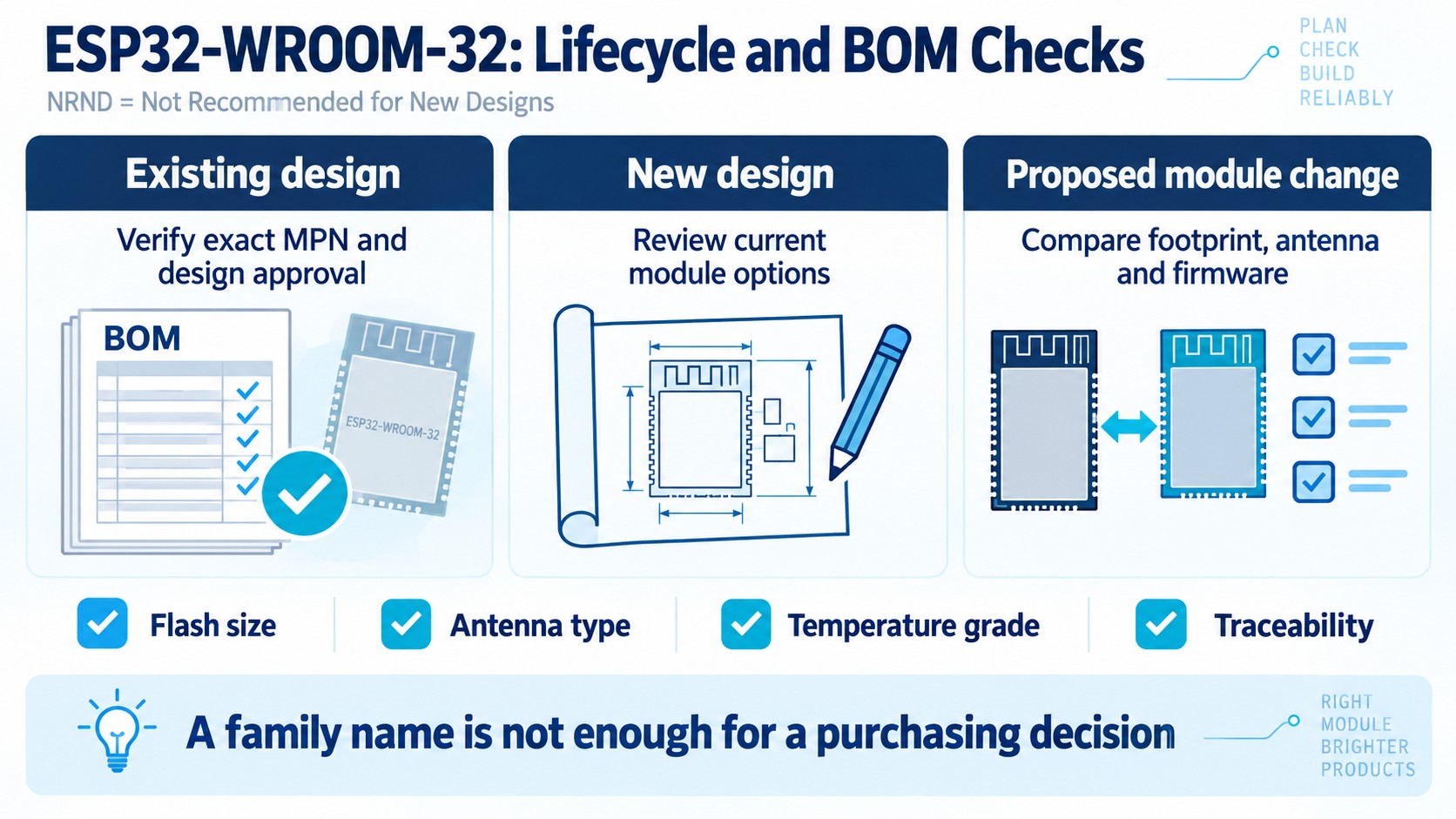
For an existing approved BOM, review the ESP32-WROOM-32 product record, including its NRND note and specifications. Send the exact requirements for an RFQ to confirm price, availability and supporting documentation for that request.
Frequently asked questions
Can ESP32-WROOM-32 run directly from 5 V?
The bare module requires 3.0–3.6 V at its supply input. A development board may accept 5 V through additional regulator circuitry; check that board's schematic before using the same connection on a carrier PCB.
Is ESP32-WROOM-32 a development board?
It is a surface-mount wireless MCU module. USB connectors, programming interfaces, buttons and voltage regulators found on a development board are additional board hardware.
Why does a custom board fail to enter the serial bootloader?
Check EN, supply stability and the levels on GPIO0 and GPIO2 during reset. Then inspect external loads on strapping signals and any automatic reset circuitry. The boot-mode guide provides the expected conditions and log interpretation.
Are GPIO32 and GPIO33 input-only?
No. They support input and output. The exposed input-only signals discussed here are GPIO34, GPIO35, GPIO36 and GPIO39; use the original module's pin table for the complete mapping.
Can I replace the original module with ESP32-WROOM-32E or 32UE?
Compare the exact proposed order code and validate the board and firmware before approving the change. Antenna type, Flash configuration and mechanical requirements need explicit review; a related family name alone is insufficient.
Reviewed October 10, 2026 against Espressif ESP32-WROOM-32 datasheet v3.8 and the linked hardware and software documentation. Illustrations are conceptual; release hardware using the manufacturer's current drawings and your approved design records.