
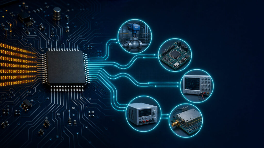
A DAC is used to turn digital commands into controlled analog voltage or current outputs. In practical electronics, that means a processor, microcontroller, FPGA, or digital controller can set a real analog level for control, calibration, waveform generation, biasing, tuning, or signal output.
For component buyers, the useful question is not whether a DAC is "better" in a consumer audio chain. The useful question is whether your design needs a repeatable analog output with the right resolution, output range, speed, accuracy, interface, channel count, and sourcing path. Start from ApexComponent's digital-to-analog converter ICs category to compare DAC ICs for your application.
| Application Need | How a DAC Helps | First Specs to Check |
|---|---|---|
| PLC or industrial control output | Produces analog setpoints such as voltage or current commands | Output range, load drive, accuracy, isolation needs, temperature range |
| MCU analog-output expansion | Adds a true analog output when GPIO, PWM, or internal DAC is not enough | Interface, resolution, update rate, reference, package |
| Calibration and trimming | Stores or updates offset, gain, threshold, or reference values | Resolution, nonlinearity, drift, EEPROM or register behavior |
| Signal generation | Converts digital samples into analog waveforms or stepped levels | Update rate, settling time, glitch energy, output filter needs |
| Bias, tuning, and RF control | Sets bias voltages, tuning levels, gain-control points, or baseband signals | Noise, monotonicity, settling, output compliance, layout constraints |
What Is a DAC Used For?
A DAC, or digital-to-analog converter, is used when a digital system must create an analog output. The digital input may be a binary code, a serial command, a sample stream, or a register value. The analog output may be a voltage, a current, or a signal that is later buffered, filtered, amplified, or level-shifted.
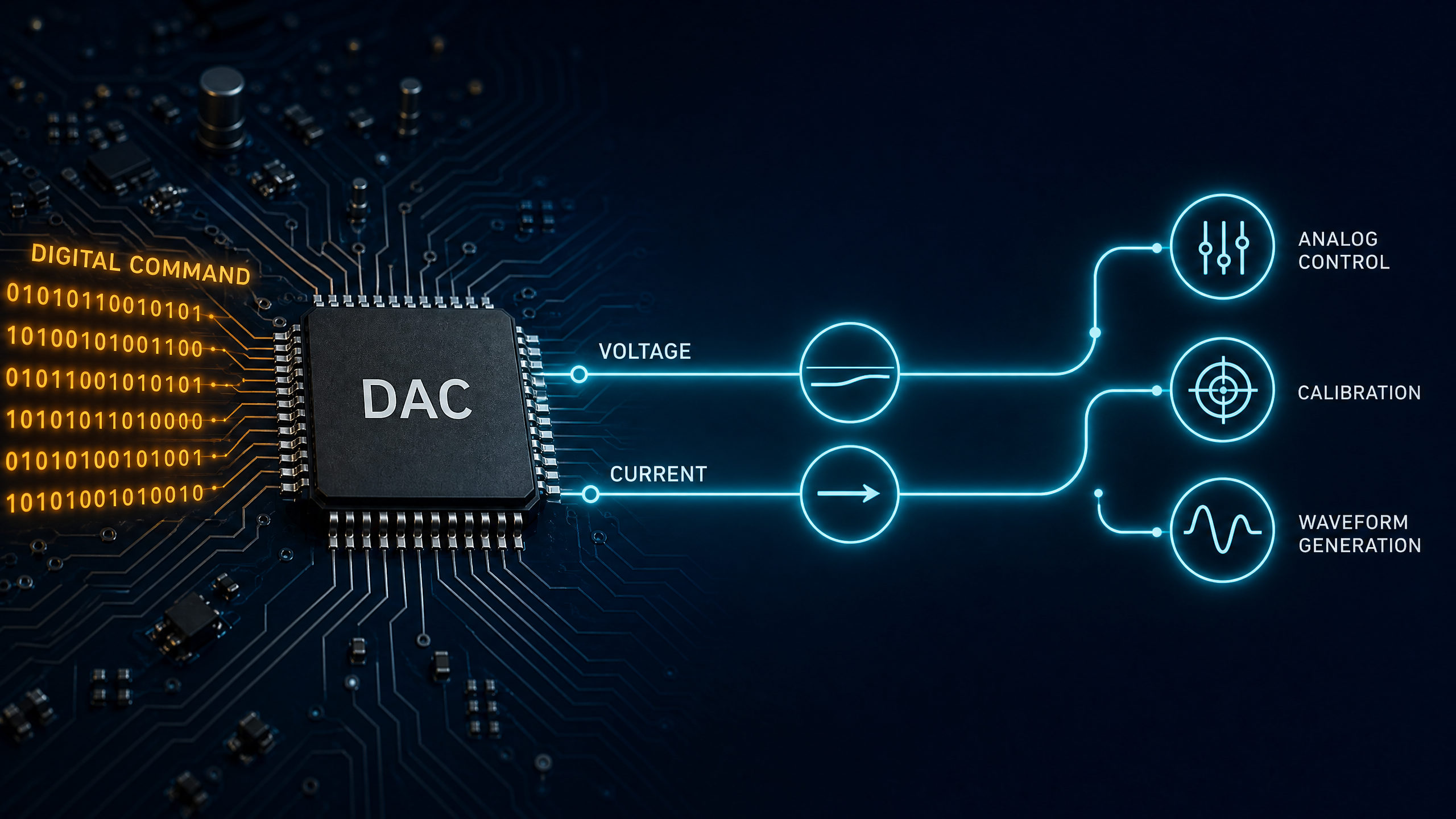
Texas Instruments describes a DAC as a converter that maps a limited number of digital input codes to corresponding analog output values. That definition matters for design: a DAC output is not infinitely continuous. It changes in finite steps set by resolution, reference voltage, output architecture, and the DAC transfer function.
Common digital-to-analog converter applications in B2B electronics include industrial automation, embedded control, test and measurement, programmable power equipment, RF control, and communications support circuits. The core sourcing lesson is simple: a DAC used for slow calibration does not need the same update rate as a DAC used for waveform generation, and a DAC used for a PLC output does not have the same output-stage needs as a small I2C DAC connected to a microcontroller.
Analog Control Outputs for PLCs, Actuators, and Process Equipment
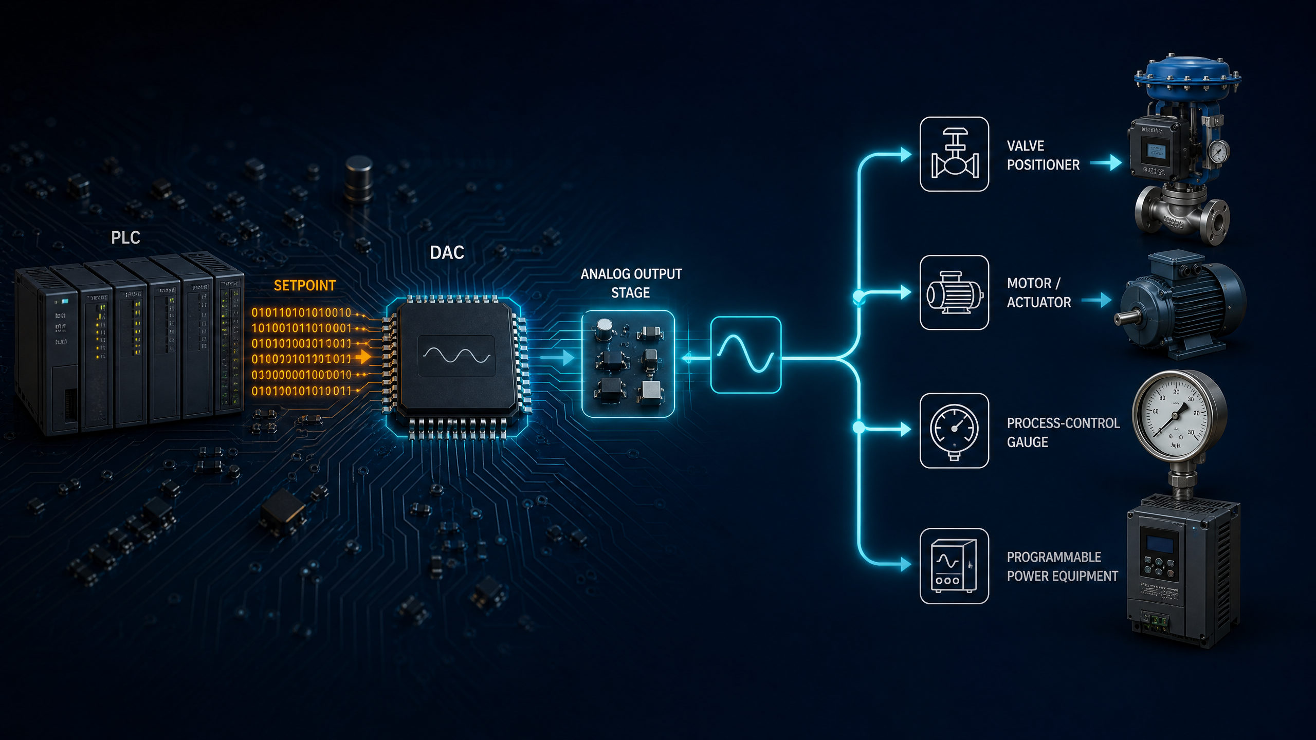
Industrial systems often use analog outputs because many field devices still accept proportional analog commands. A PLC, motion controller, or process controller may calculate a digital control value, then use a DAC and output stage to generate an analog command.
| Industrial Application | DAC-Controlled Output | Design Notes |
|---|---|---|
| Valve position control | Analog voltage or current setpoint | Check output range, drive capability, protection, and fault behavior |
| Motor or actuator command | Speed, torque, position, or current reference | Match update rate and settling time to control-loop needs |
| Process control | Temperature, flow, pressure, or level command | Watch drift, accuracy, and environmental ratings |
| Programmable power equipment | Voltage or current setpoint | Check reference accuracy, monotonicity, and startup state |
| Analog output module | Multi-channel output generation | Channel count, isolation, calibration, and package density matter |
For industrial buyers, the DAC IC is only one part of the analog output chain. The full circuit may also need a voltage reference, output amplifier, protection network, isolation, filtering, and calibration. Do not assume the DAC can directly drive the field load unless the datasheet and output-stage design support that load.
Two procurement risks are common. First, engineers may specify only the resolution, such as "12-bit DAC" or "16-bit DAC," without documenting the analog output range, reference, load, interface, or temperature range. Second, purchasing teams may treat two DACs with the same bit count as interchangeable even when output architecture, pinout, package, interface timing, and software initialization differ. Do not assume drop-in compatibility from resolution or interface alone. Compare the exact datasheets for pinout, package drawing, supply rails, output type, reference input, code format, timing, power-up state, temperature grade, compliance, and software/register behavior; then approve the alternate only after board-level validation.
For a deeper selection checklist, read How to Choose a Good DAC IC.
MCU and FPGA Analog-Output Expansion
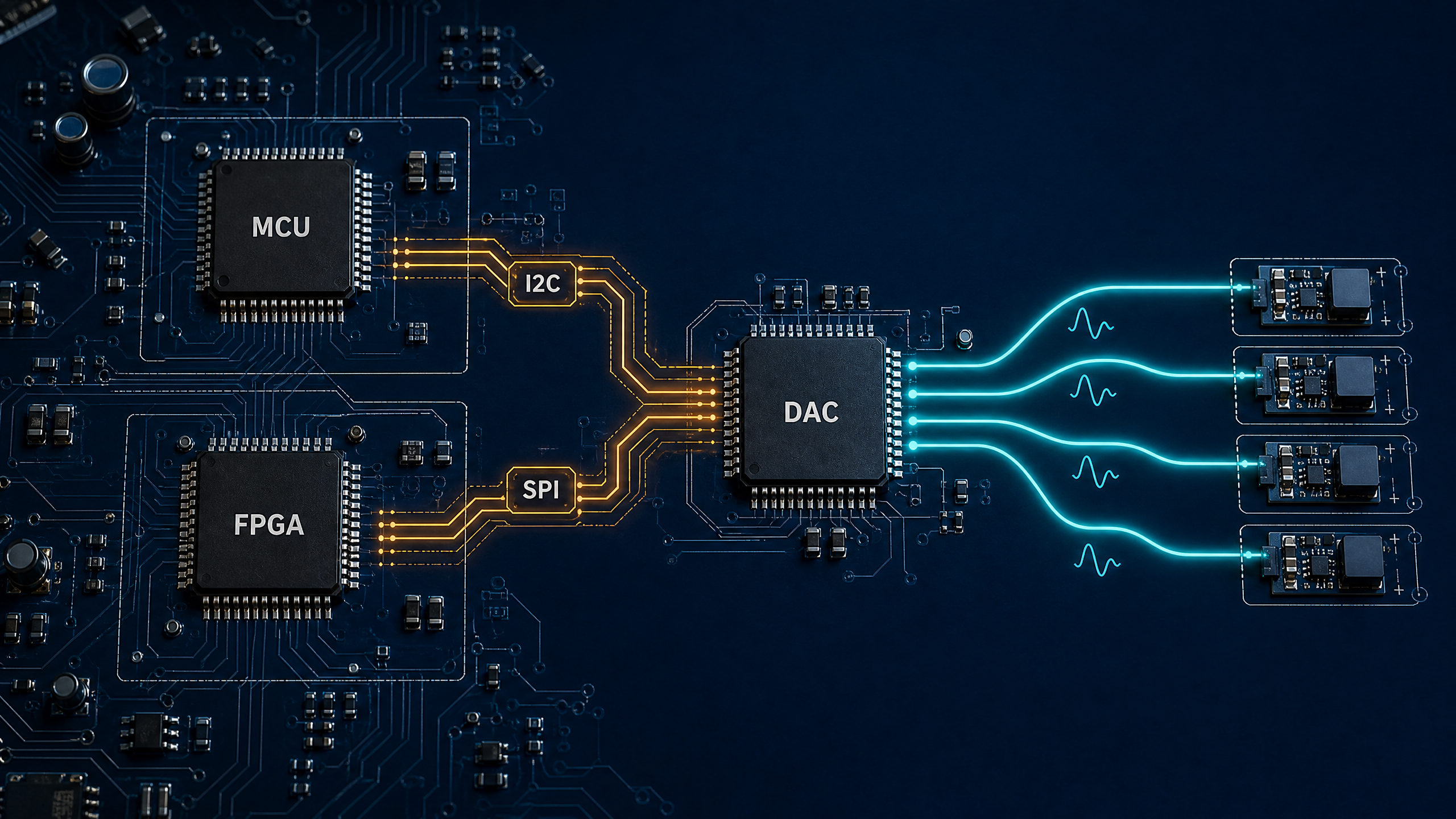
Many embedded systems need at least one analog output, but not every microcontroller has a suitable built-in DAC. Even when an MCU includes an internal DAC, the external circuit may require better resolution, lower noise, more channels, a different reference, a different output range, or isolation from the digital processor.
| Embedded Need | Why an External DAC May Help |
|---|---|
| Add a real analog output to an MCU without one | GPIO pins are digital; PWM needs filtering and may not meet ripple or response targets |
| Improve output accuracy or resolution | External DACs may offer specs not available in the internal DAC block |
| Add more analog output channels | Multi-channel DACs can simplify board routing and firmware control |
| Place the analog output near the load | Board partitioning can reduce noise pickup and simplify analog layout |
| Use a simple serial interface | I2C DAC and SPI DAC devices reduce pin count compared with parallel DACs |
When a design needs an analog output from a microcontroller, the usual decision is between PWM, the MCU's internal DAC, and an external DAC IC. PWM can be enough for dimming, coarse control, or slow filtered outputs. A true DAC is stronger when the application needs a defined analog level, faster response without heavy filtering, lower ripple, finer steps, or cleaner behavior over code transitions.
I2C DACs are common in compact embedded designs because they use few digital pins and fit slow to moderate update applications. Microchip's MCP4725 is one example of a 12-bit voltage-output DAC with an I2C interface and nonvolatile memory. It is not automatically the right part for every project; it is simply a common I2C DAC example for MCU analog-output expansion. Current availability, package options, pricing, lead time, and whether the device is still recommended for new designs must be checked against current manufacturer or distributor data during sourcing.
If the design choice is still open, compare the tradeoffs in Built-In DAC vs External DAC IC. If the project may not need a DAC at all, start with Do You Need a DAC IC?.
Signal Generation, Calibration, and Programmable References
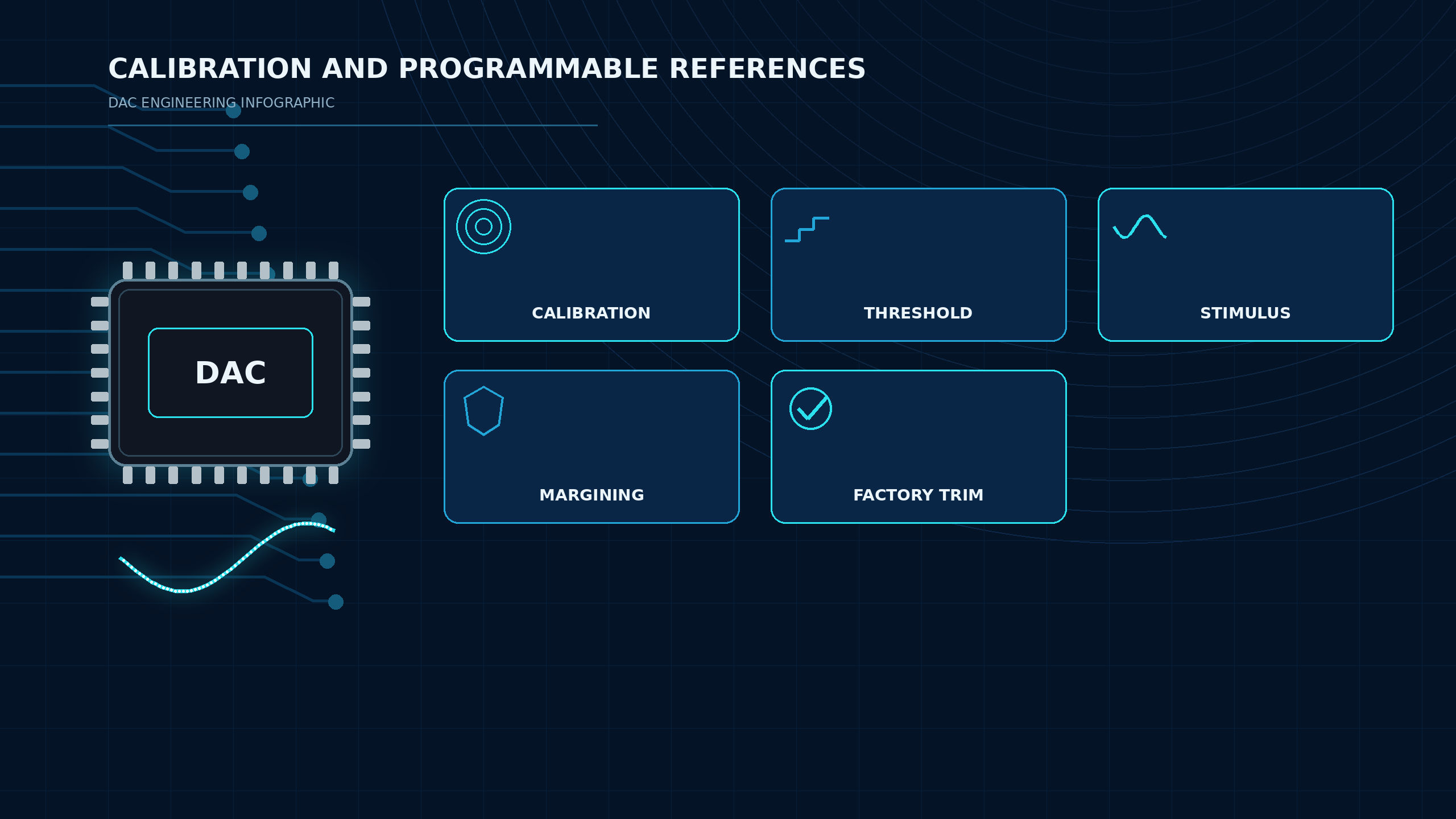
DACs are also used when a system needs a programmable analog signal rather than a fixed resistor divider, potentiometer, or reference value. The DAC lets firmware update the output level without changing hardware.
| Application | DAC Function | Important Requirements |
|---|---|---|
| Sensor calibration | Apply offset or gain correction | Resolution, drift, nonvolatile setting behavior |
| Programmable threshold | Set comparator or protection trip point | Accuracy, startup value, noise, reference stability |
| Instrument stimulus | Generate test level or stepped output | Linearity, settling time, output amplifier performance |
| Power-supply margining | Adjust feedback or reference node | Output range, fault behavior, monotonicity |
| Factory trim | Replace manual trimming with digital calibration | EEPROM, write endurance, calibration procedure |
The DAC's reference source is central in these uses. If the reference drifts, the DAC output can drift even when the digital code is unchanged. If the output buffer cannot settle quickly enough, the next measurement or control action may start before the analog value is valid. If the DAC is nonmonotonic in the operating region, a higher digital code may not always produce a higher analog output, which can be unacceptable in control and calibration systems.
TI's precision data-converter selection guidance emphasizes that DAC choice depends on functional parameters and how those parameters affect system capability. For procurement, that means a sourcing request should include more than bit count. Include output type, supply voltage, reference approach, interface, channel count, output range, temperature requirements, package preference, and whether nonvolatile memory is required.
For signal quality topics such as noise, settling, reference behavior, and linearity, see Will a DAC Improve Signal Quality?.
Waveform, Bias, Tuning, and RF-Related Control Signals
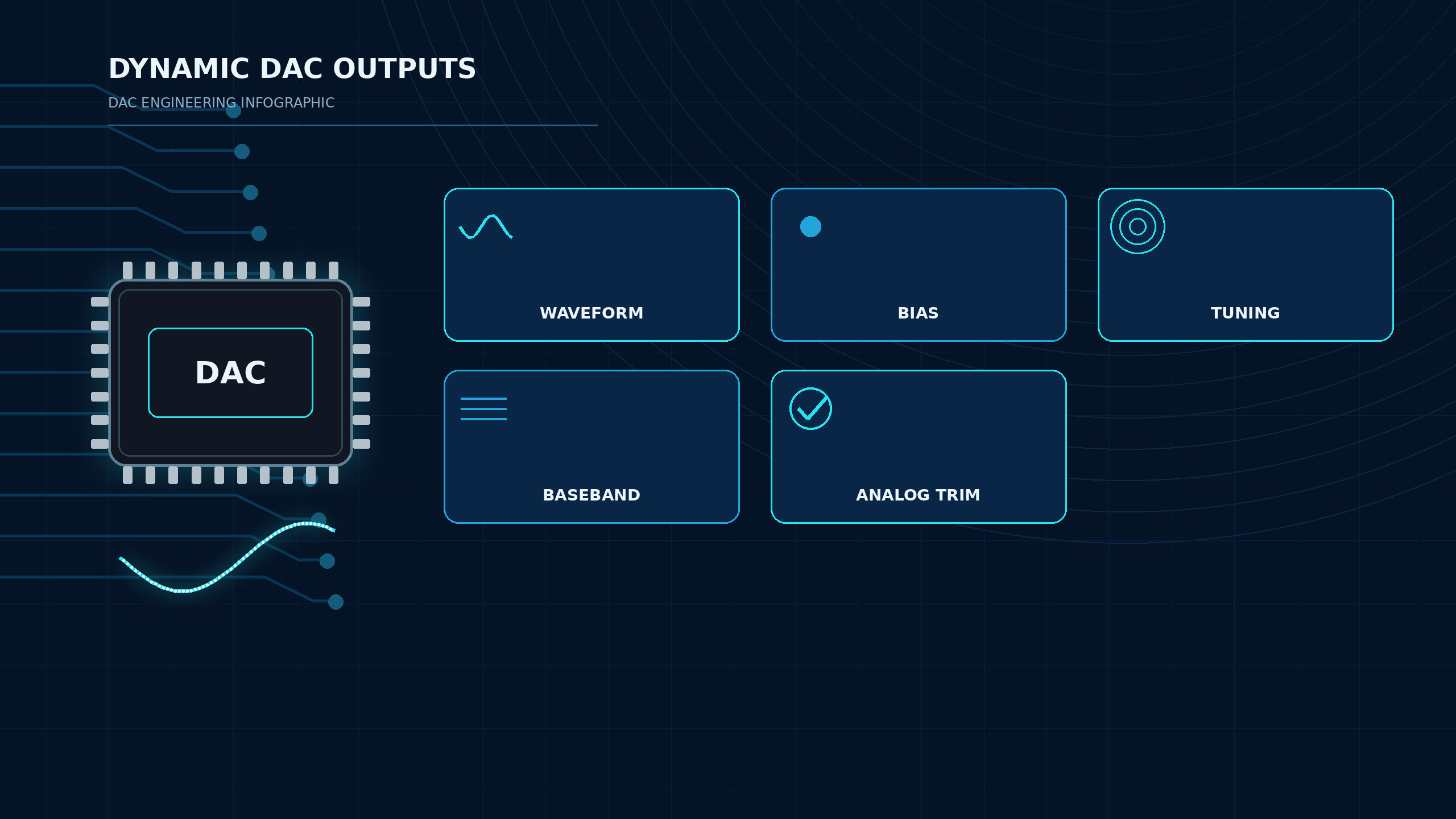
Some DAC applications are dynamic. The DAC may generate a waveform, update a control loop, bias an amplifier, tune an oscillator, control a variable-gain stage, or create an RF/baseband-related signal. These cases usually care more about timing, glitch energy, output noise, and analog output architecture than slow calibration applications do.
TI's high-speed DAC application note covers topics such as sampling theory, datasheet parameters, and performance considerations for high-speed digital-to-analog conversion. In practical terms, that means waveform and RF-related uses should not be sourced with only "12-bit" or "16-bit" in the BOM note. The update rate, settling behavior, output spectrum, clocking, layout, reconstruction filtering, and downstream analog stage can be just as important as the resolution.
| Dynamic Use | DAC Output Role | What to Watch |
|---|---|---|
| Arbitrary waveform generation | Converts sample codes into an analog waveform | Update rate, output filter, glitch, spectral performance |
| Bias control | Sets transistor, amplifier, sensor, or photonic bias level | Noise, drift, output compliance, startup sequencing |
| Tuning voltage | Controls VCOs, filters, gain blocks, or tunable circuits | Resolution, monotonicity, settling, reference noise |
| Baseband or IF support | Produces controlled analog signals for communication chains | Speed, output architecture, layout, clocking |
| Programmable analog trim | Adjusts offset, gain, or operating point | Stability, temperature behavior, calibration retention |
RF-related control does not mean every DAC must be a very high-speed converter. A slow control DAC may set a tuning or bias voltage in an RF system, while a high-speed DAC may synthesize or reconstruct a signal path waveform. Those are different procurement classes. The BOM should make that distinction clear.
Application Requirements That Affect DAC Choice
The best DAC for an application depends on the analog output requirement, not only on the part's bit count or product category. Before requesting a quote or approving a substitute, document these requirements:
| Requirement | Why It Matters |
|---|---|
| Resolution | Sets the number of output steps; higher bit count is useful only if noise, reference, and accuracy support it |
| Output range | Must match the circuit input, actuator command, reference node, or output driver |
| Output type | Voltage-output and current-output DACs need different support circuits |
| Accuracy and linearity | INL, DNL, gain error, offset error, and drift affect control precision |
| Settling time / update rate | Determines whether the output reaches the target value before the next operation |
| Interface | I2C, SPI, parallel, JESD, or other interfaces change firmware, pin count, and speed |
| Channel count | Multi-channel DACs can reduce BOM count but may add crosstalk or layout constraints |
| Reference | Internal vs external reference affects drift, noise, accuracy, and board cost |
| Package and temperature | Must fit board, assembly, thermal, and environmental requirements |
| Lifecycle and sourcing | Active status, alternates, and approved manufacturers affect long-term procurement risk |
Stock, price, lead time, date-code limits, region, packaging method, and compliance documents are order-specific sourcing data. Do not publish them as fixed technical facts. For a production quote, send the full manufacturer part number, package suffix, quantity, target delivery date, required date code, RoHS/REACH or automotive requirement, and approved alternates so the supplier can confirm current availability and terms.
Need DAC IC for MCU-controlled analog output.
Preferred interface: I2C or SPI.
Resolution target: 12-bit minimum, 16-bit preferred if cost/availability supports it.
Output: voltage output, 0 V to 3.3 V or configurable range.
Channels: 1 to 4.
Application: programmable control setpoint, slow update.
Package: SOT-23, MSOP, TSSOP, QFN, or equivalent board-approved package.
Dynamic sourcing data: confirm stock, price, lead time, lifecycle, and approved alternates.
This is more useful than sending only "need DAC" or "need 16-bit DAC." It gives engineering and sourcing teams a shared basis for comparison.
Common Mistakes
Mistake 1: Treating Consumer Audio DAC Questions as DAC IC Sourcing Requirements
USB DACs, headphone DACs, DAPs, speakers, and expensive consumer audio upgrades are finished products, not the ICs covered by this guide. This article focuses on DAC ICs for control, embedded systems, instrumentation, calibration, waveform generation, and procurement.
Mistake 2: Choosing Only by Bit Count
Resolution matters, but it is not the whole device. A 16-bit DAC with poor reference design, unsuitable output range, slow settling, or the wrong interface may perform worse in the actual circuit than a lower-resolution part selected correctly.
Mistake 3: Assuming PWM Is Always Equivalent to a DAC
PWM plus filtering can create an average voltage, but ripple, response time, filter size, load interaction, and startup behavior may make it unsuitable. A DAC is usually preferred when the design needs a defined analog level with controlled accuracy and response.
Mistake 4: Approving a Substitute Without Pinout and Behavior Checks
Two DACs can share resolution and interface but differ in register map, reference behavior, output buffer, address options, power-on state, package, and pinout. Do not assume drop-in compatibility from resolution or interface alone. Compare the exact datasheets for pinout, package drawing, supply rails, output type, reference input, code format, timing, power-up state, temperature grade, compliance, and software/register behavior; then approve the alternate only after board-level validation.
Related Reading
- What Is a Digital-to-Analog Converter? — how a DAC maps digital codes to analog levels and how it differs from an ADC.
- How to Choose a Good DAC IC — a step-by-step selection checklist for buyers.
- Built-In DAC vs External DAC IC — when an external DAC is worth the added part.
- Do You Need a DAC IC? — how to decide before adding a DAC to the BOM.
- Will a DAC Improve Signal Quality? — resolution, reference, noise, settling, and linearity.
- Digital-to-Analog Converter ICs — the ApexComponent DAC IC category for sourcing review.
FAQ
What is a DAC used for?
A DAC is used to convert digital commands or codes into analog voltage or current outputs. Common uses include industrial control outputs, MCU analog-output expansion, calibration, programmable references, waveform generation, bias control, and tuning signals.
What are common digital to analog converter applications?
Common digital to analog converter applications include PLC output modules, actuator setpoints, programmable power supplies, test equipment, data acquisition support circuits, sensor calibration, waveform generation, and embedded analog-output expansion.
Why use a DAC with a microcontroller?
Use a DAC with a microcontroller when the MCU needs a real analog output rather than a digital GPIO state or filtered PWM signal. External DACs can add channels, improve resolution, support I2C or SPI control, or meet analog performance requirements that the internal MCU DAC cannot meet.
What is an I2C DAC used for?
An I2C DAC is used when a design needs a low-pin-count serial DAC for slow to moderate analog-output updates. Typical uses include setpoints, calibration levels, small embedded control outputs, and programmable references.
Can a DAC control a motor directly?
Usually no. A DAC normally creates a control voltage or reference signal. Motor current, voltage, and protection are handled by driver circuitry, power stages, or controllers. Always verify the load and output-stage requirements.
Does a DAC improve signal quality?
A DAC can improve an analog output if the previous approach had poor resolution, ripple, noise, drift, or response. It cannot fix a poor reference, bad layout, unsuitable output amplifier, overloaded output, or incorrect system architecture.
Is every DAC IC interchangeable?
No. DAC ICs differ by output type, resolution, interface, reference design, channel count, package, power-on behavior, register map, timing, temperature range, and lifecycle status. Do not assume drop-in compatibility from resolution or interface alone. Compare the exact datasheets for pinout, package drawing, supply rails, output type, reference input, code format, timing, power-up state, temperature grade, compliance, and software/register behavior; then approve the alternate only after board-level validation.
Find DAC ICs for Your Application
Find DAC ICs for your application. Use the ApexComponent digital-to-analog converter ICs category to shortlist parts by resolution, output type, interface, reference, package, and lifecycle.
Use Send Inquiry when the DAC is part of an embedded, industrial, calibration, waveform, or mixed-signal project. Include candidate part numbers if available, plus the application, output range, interface, package constraints, approved manufacturers, quantity, delivery date, compliance needs, and acceptable alternates.
References and Further Reading
- Texas Instruments, "High-Speed, Digital-to-Analog Converters Basics" (SLAA523) — https://www.ti.com/lit/pdf/slaa523
- Texas Instruments, "Precision Data Converter Selection Guide" (SDAA326) — https://www.ti.com/lit/pdf/sdaa326
- Texas Instruments, Digital-to-Analog Converters (DACs) overview — https://www.ti.com/product-category/data-converters/dacs/overview.html
- Analog Devices, "DAC Interface Fundamentals" (MT-019) — https://www.analog.com/MT-019
- Analog Devices, Digital-to-Analog Converters (DACs) category — https://www.analog.com/en/product-category/digital-to-analog-converters.html
- Microchip, MCP4725 product page and datasheet — https://www.microchip.com/en-us/product/mcp4725
- Electronics Tutorials, "Digital to Analogue Converter and Binary Weighted DACs" — https://www.electronics-tutorials.ws/combination/digital-to-analogue-converter.html