
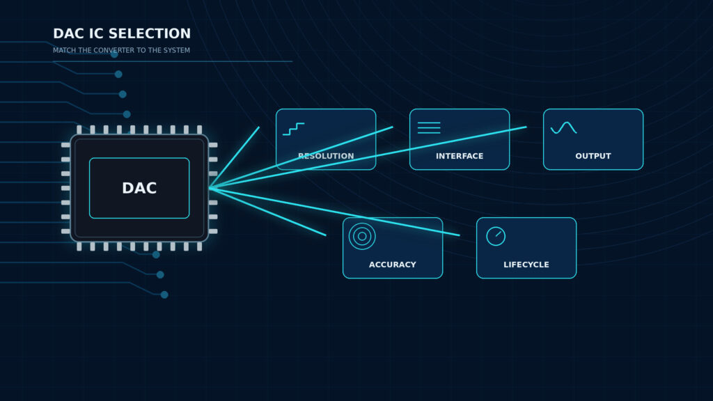
A good DAC IC is not the part with the highest bit count on the first search result. It is the digital-to-analog converter that matches the required output range, control interface, accuracy, speed, reference architecture, package, lifecycle, and sourcing path for the real design. If you are comparing active DAC parts for a PCB, start from ApexComponent's digital-to-analog converter ICs category, then narrow the choice with the engineering and purchasing checks below.
For a buyer, the main risk is ordering a part that looks correct by resolution but fails on interface, output drive, accuracy, package, or lifecycle. For an engineer, the main risk is treating all DACs as interchangeable voltage sources. This guide gives a practical framework for choosing a DAC IC and preparing a sourcing request that a supplier can quote without repeated clarification.
Quick Take: DAC IC Selection Table
| Selection item | What to check | Good fit | Procurement note |
|---|---|---|---|
| Resolution | Number of output codes, such as 8, 12, 16, or 24 bits | Match the smallest analog step your system can use | Higher resolution may raise cost and sourcing constraints |
| Interface | I2C, SPI, or parallel | Match MCU/FPGA pins, update speed, and bus topology | Confirm exact ordering code and package before quote |
| Output type | Voltage-output or current-output | Voltage output for direct control levels; current output for specialized signal chains | Output stage and external amplifier needs affect BOM cost |
| Accuracy | INL, DNL, offset, gain error, noise, reference, drift | Match the real error budget, not only the bit count | Datasheet conditions must be checked line by line |
| Lifecycle | Active, NRND, obsolete, last-time buy | Active or approved long-life part for new designs | Check the manufacturer product page, PCN/PDN notices, and authorized-distributor lifecycle status before volume approval |
1. How to Choose a Good DAC IC
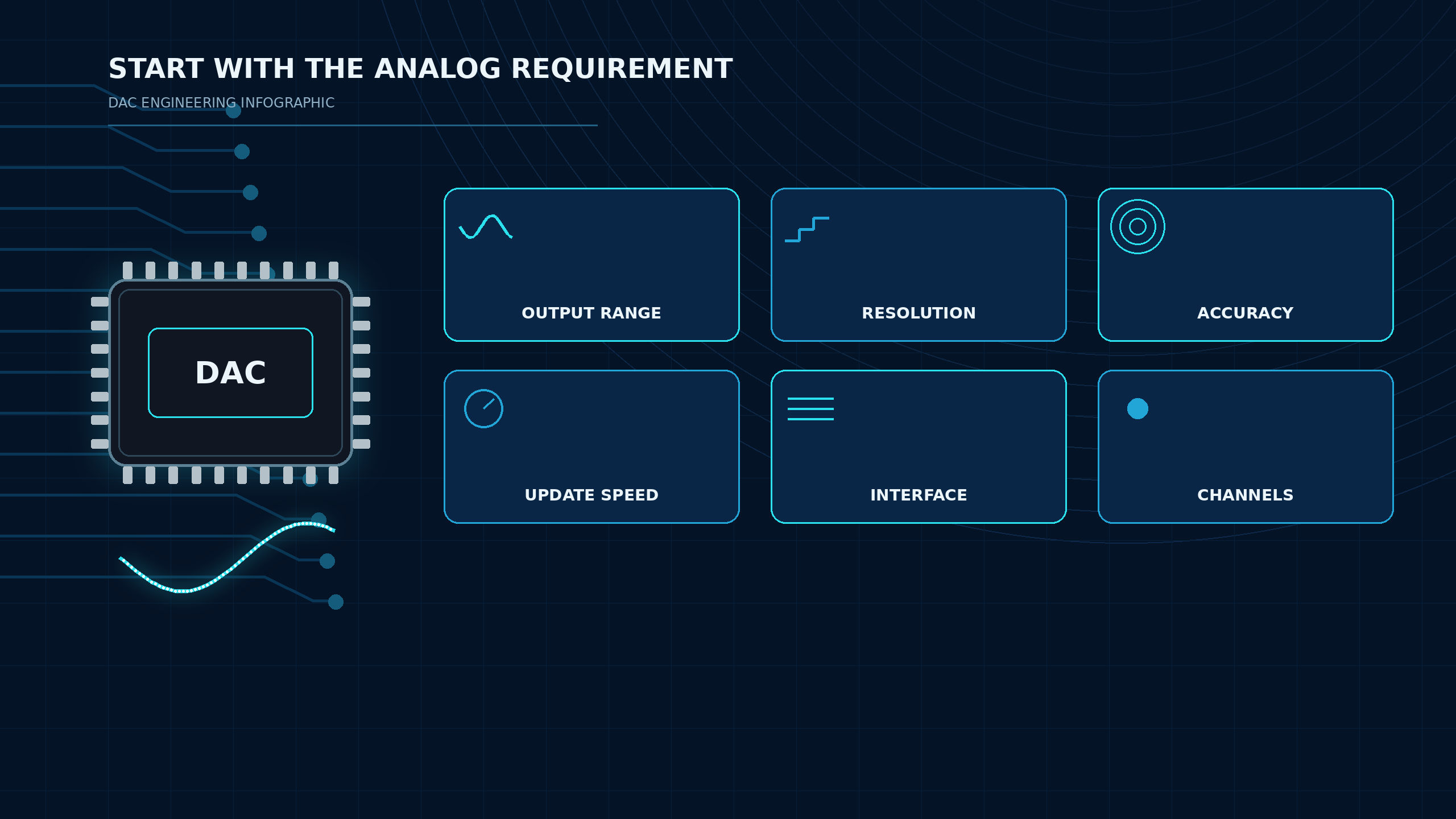
Start by writing the analog-output requirement before looking at part numbers. A useful DAC requirement includes output range, required resolution, accuracy budget, update behavior, digital interface, channel count, supply rails, reference architecture, operating temperature, package constraints, and procurement requirements.
This order matters. If you begin with "16-bit DAC" only, you may miss a 12-bit part that is accurate enough, cheaper to source, and easier to route. You may also choose a 16-bit digital to analog converter whose real total error is worse than the usable accuracy of the system because the reference, noise, offset, or temperature drift was ignored. For signal-quality tradeoffs, see Will a DAC Improve Signal Quality?.
2. 8-Bit, 12-Bit, 16-Bit, and 24-Bit DACs
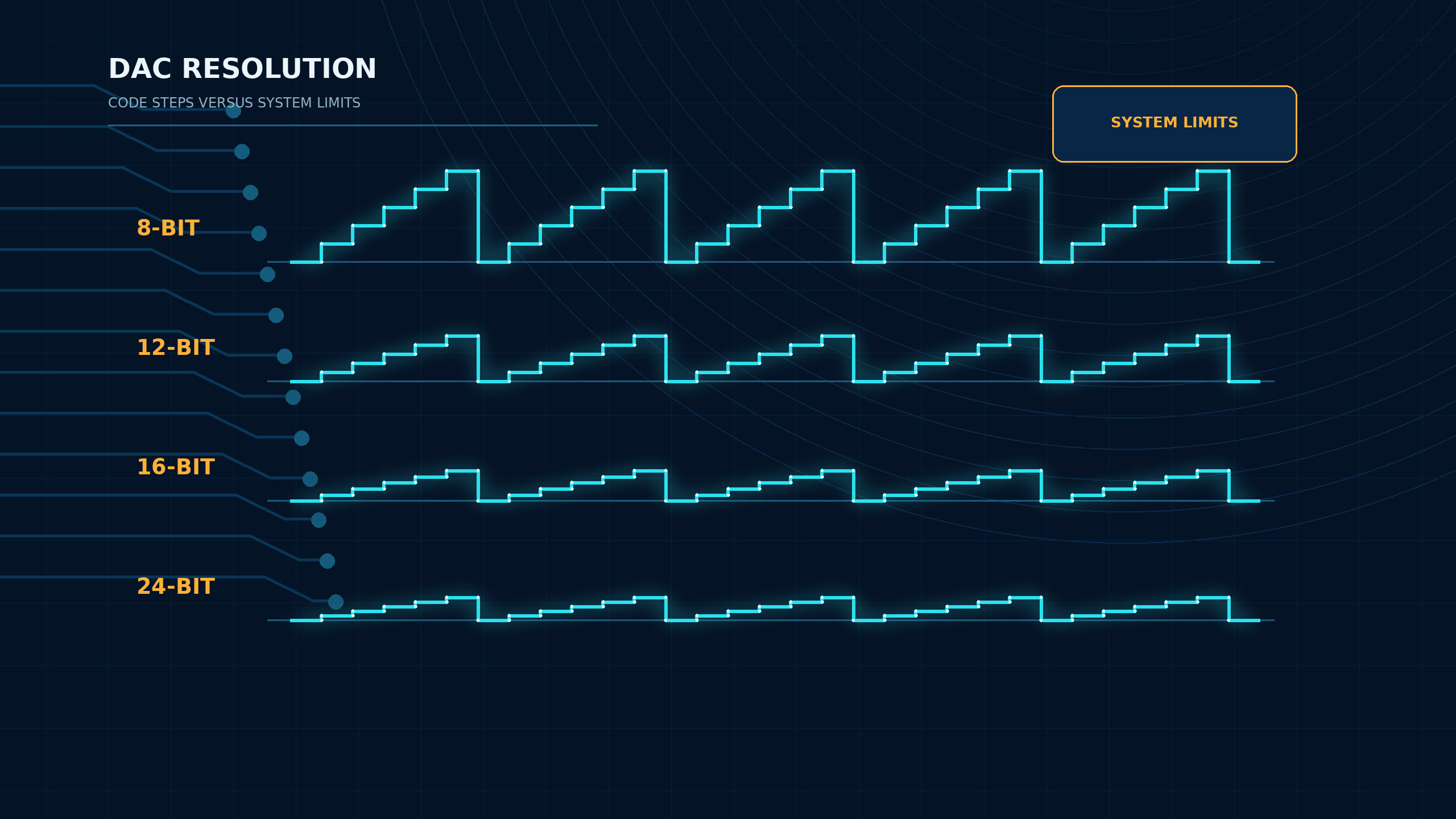
Resolution tells you how many digital input codes the DAC can convert into output levels. An N-bit DAC has 2^N possible codes. That means 8-bit provides 256 codes, 12-bit provides 4,096 codes, 16-bit provides 65,536 codes, and 24-bit provides more than 16 million codes. The step size depends on the reference and output range, so bit count alone does not define accuracy.
| DAC resolution | Typical selection use | What it does well | Main caution |
|---|---|---|---|
| 8-bit DAC | Simple bias, trimming, coarse control, legacy circuits | Low data width and simple control | Not enough granularity for precision control |
| 12-bit DAC | MCU expansion, sensor calibration, industrial setpoints | Good balance of resolution, cost, and availability | Check offset, gain error, and reference before calling it precise |
| 16-bit DAC | Precision control, test equipment, programmable references | Fine step size and strong fit for precision analog output | Real accuracy may be limited by INL, noise, drift, PCB layout, and reference |
| 24-bit DAC | Specialized precision or instrumentation niches | Very fine digital code granularity | Not automatically useful in noisy or drift-limited systems |
3. I2C, SPI, and Parallel DAC ICs
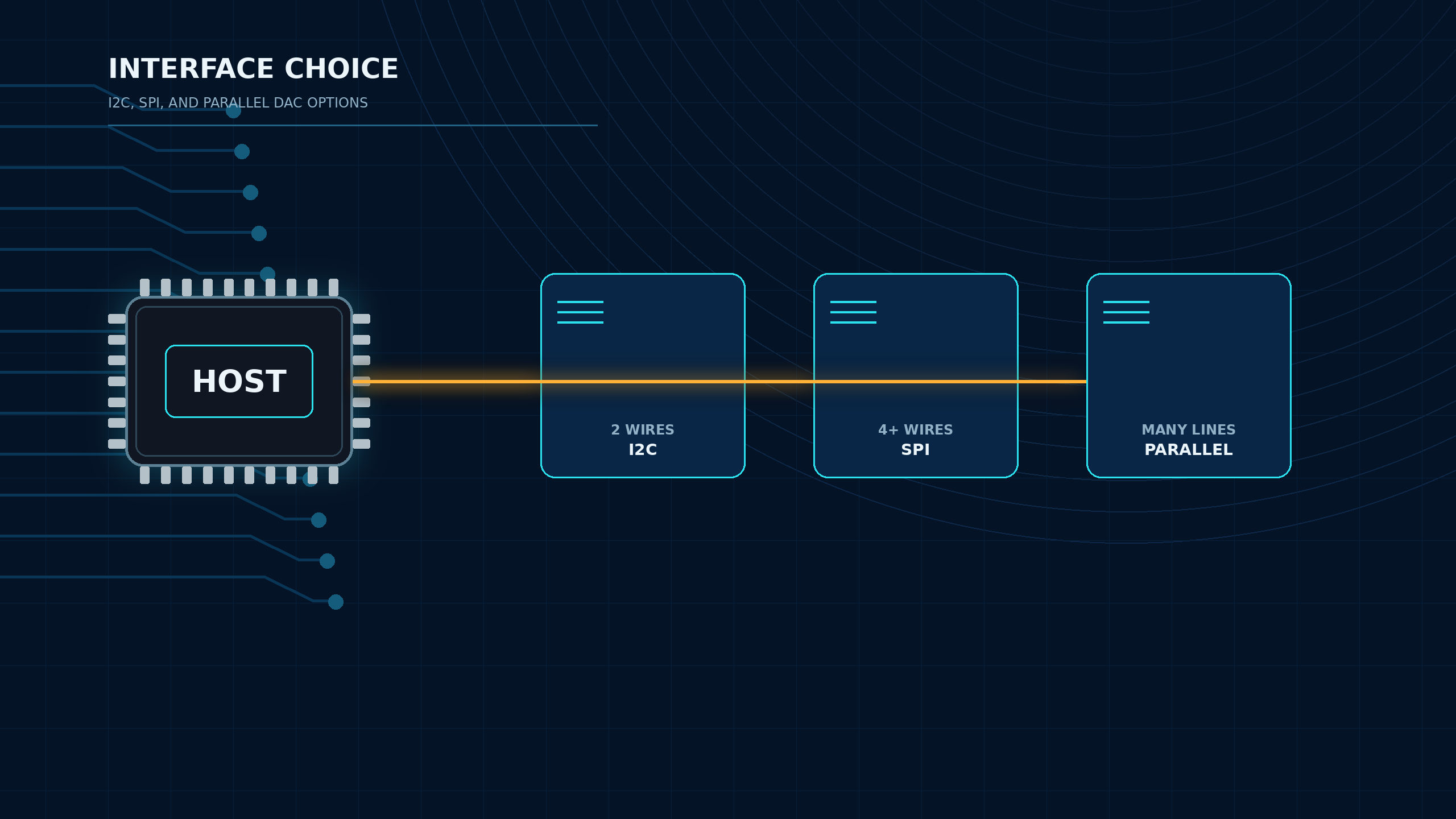
Interface choice affects firmware complexity, pin count, update rate, board routing, and part availability. An I2C DAC is often attractive for MCU designs because it uses few pins and can share a bus with other devices. SPI DACs usually fit designs that need faster updates, cleaner timing control, or multiple synchronized devices. Parallel DAC ICs use more pins and board space, but they can support high update speeds and deterministic timing in FPGA, waveform, or legacy designs.
| Interface | Best fit | Advantages | Watch-outs |
|---|---|---|---|
| I2C DAC | Low-pin-count MCU control, setpoints, calibration, slow control loops | Two-wire bus, simple system expansion, addressable devices | Bus speed, address conflicts, latency, and limited high-speed waveform use |
| SPI DAC | Precision control, faster update, synchronized channels | Higher throughput, simple framing, good timing control | More pins, chip-select routing, firmware timing requirements |
| Parallel DAC | High-speed update, legacy bus systems, FPGA output | Fast data loading and deterministic timing | High pin count, routing complexity, package and lifecycle risk |
If the host already has a built-in DAC, compare the internal block against the external DAC IC requirement before adding another component. The article Built-In DAC vs External DAC IC covers that decision in more detail.
4. Voltage-Output vs Current-Output DAC
Voltage-output DACs are usually easier to apply when the design needs a programmable voltage level. Many include an output buffer, but the datasheet still needs to be checked for output swing, load capability, capacitive-load stability, short-circuit behavior, and settling time.
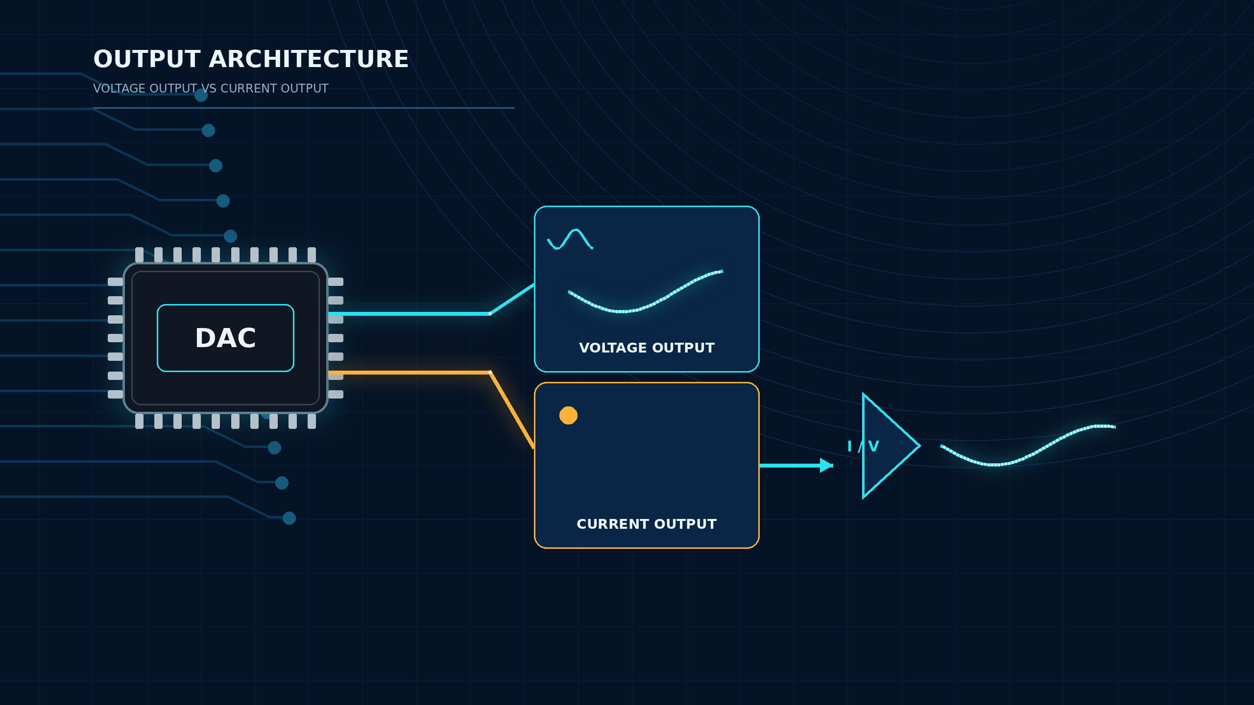
Current-output DACs deliver a current proportional to the digital code and often require an external current-to-voltage stage, such as an op amp transimpedance circuit. They can be useful in high-speed signal paths, multiplying DAC applications, waveform generation, or systems where the analog output stage must be designed around a specific load or compliance voltage.
For procurement, the output type changes the quote request. A voltage-output part may be quoted as a single IC line item. A current-output part may require the buyer to confirm the op amp, feedback components, reference source, and layout constraints with engineering before approval.
5. INL/DNL, Noise, Reference, Settling Time, and Temperature Drift
The most common DAC selection mistake is equating resolution with usable accuracy. A 16-bit DAC has fine digital code spacing, but the actual output depends on INL, DNL, offset error, gain error, noise, reference error, settling time, and temperature drift.
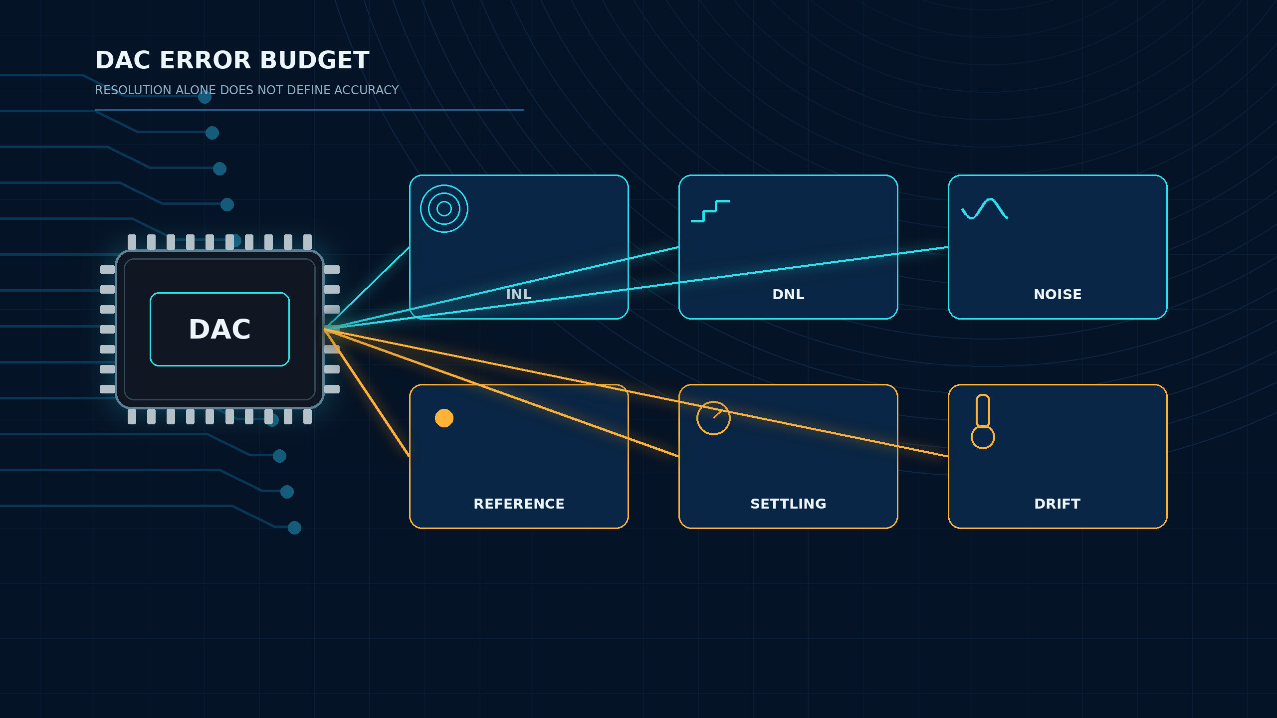
These are not only engineering details. They determine whether a cheaper DAC can be used, whether a more expensive precision DAC is justified, and whether the supplier must source a matching voltage reference. For example, if a control loop updates only a few times per second, ultra-fast settling may not matter. If a calibration system must hold a stable output across temperature, reference drift and DAC drift may matter more than interface speed.
When reading a datasheet, record the test conditions. INL may be specified over a certain code range and supply condition. Settling time may be specified for a particular code step, output load, and error band. Noise may depend on bandwidth. Temperature drift may be typical rather than maximum. If a condition is missing from the available document, ask the supplier for the exact datasheet revision, manufacturer product page, or written manufacturer confirmation before approving the part.
6. DAC IC Sourcing Checklist
Use this checklist before sending an RFQ or approving a BOM substitution.
| Checkpoint | What to send or verify | Why it matters |
|---|---|---|
| Part number | Full manufacturer part number, suffix, package, and packaging type | Prevents ordering a similar but wrong reel, tube, tray, or package |
| Resolution and channels | Required bits and number of DAC outputs | Avoids overbuying resolution or missing channel density |
| Interface | I2C, SPI, parallel, address pins, logic level | Confirms MCU/FPGA compatibility |
| Output architecture | Voltage-output, current-output, buffered, unbuffered | Defines external amplifier and load requirements |
| Reference | Internal reference, external reference, reference voltage, tolerance, drift | Sets full-scale accuracy and may create another sourcing line |
| Accuracy | INL, DNL, offset, gain error, monotonicity, noise | Verifies actual usable precision |
| Package | SOIC, MSOP, TSSOP, QFN, WLCSP, or other package | Match the package drawing, land pattern, height, assembly process, thermal path, and orderable suffix before release |
| Compliance | RoHS, REACH, AEC-Q, customer approvals | Use manufacturer or authorized-supplier documentation for the exact orderable code; do not infer compliance from the base family name |
| Replacement | Pin-compatible, parametric alternative, or functional alternative | Never treat a DAC substitute as drop-in without engineering validation |
| Commercial terms | Quantity, target price, lead time, date code, origin, warranty | Confirm through a current RFQ because price and lead time vary by quantity, region, date code, packaging, and supplier allocation |
If you are still deciding whether a design needs an external converter at all, read Do You Really Need a DAC IC?. If the output is application-driven, review What Is a DAC Used For?. For lifecycle risk and replacement planning, see DAC IC Lifespan, Lifecycle, and Replacement Planning.
Common Mistakes When Choosing a DAC IC
Buying by Bit Count Only
A higher-resolution DAC can still be the wrong choice when the reference, noise, INL, temperature drift, output buffer, or layout cannot support the expected performance.
Assuming Interface Speed Equals Output Speed
A fast SPI transaction does not guarantee the analog output has settled to the required error band. Settling time must be checked from the datasheet.
Approving an Unverified Alternate
DAC replacement requires pinout, package dimensions, output architecture, reference mode, interface timing, command format, power-on behavior, temperature range, and compliance review.
Confusing Consumer Audio DACs With DAC IC Selection
USB DACs, headphone DACs, DAPs, speakers, and expensive audio DAC upgrades are finished consumer products, not the ICs covered by this guide. This article focuses on selecting DAC ICs for engineering and B2B sourcing.
Related Reading
- What Is a Digital-to-Analog Converter? — DAC basics and how codes map to analog levels.
- What Is a DAC Used For? — the applications behind DAC selection.
- Built-In DAC vs External DAC IC — decide whether an external part is needed.
- Do You Need a DAC IC? — the external-DAC decision path.
- Will a DAC Improve Signal Quality? — noise, reference, settling, and linearity.
- DAC IC Lifespan, Lifecycle, and Replacement Planning — long-term sourcing risk.
- Digital-to-Analog Converter ICs — the ApexComponent DAC IC category.
FAQ
How do I choose a good DAC IC?
Start with output range, required step size, accuracy budget, update speed, interface, output type, reference design, channel count, package, lifecycle, and sourcing requirements. Do not choose by resolution alone.
Is a 16-bit digital to analog converter always better than a 12-bit DAC?
No. A 16-bit DAC provides more digital codes, but real performance depends on INL, DNL, noise, reference accuracy, drift, output stage, and layout.
When should I use an I2C DAC?
Use an I2C DAC when the design needs low pin count, simple MCU control, and modest update speed. For faster updates, tighter timing, or synchronized outputs, SPI or parallel DAC options may be more suitable.
What is the difference between voltage-output and current-output DAC ICs?
A voltage-output DAC directly provides a programmable voltage within its output-stage limits. A current-output DAC provides a code-dependent current and usually needs an external current-to-voltage stage.
What should I include in a DAC IC RFQ?
Include full part number if known, resolution, channels, interface, output type, reference needs, supply voltage, package, temperature range, quantity, target delivery date, approved manufacturers, and acceptable alternates. Stock, price, lead time, compliance, and replacement compatibility should be treated as order-specific items: confirm them with the exact suffix, quantity, target delivery date, required date code, compliance documents, and approved-alternate rules before purchase.
Send a DAC IC Inquiry
When the DAC requirements are already defined, use Send Inquiry for the target DAC IC. Include the full manufacturer part number if known, resolution, channels, interface, output type, reference needs, supply voltage, package, temperature range, quantity, target delivery date, required date code, compliance documents, and approved alternates.
If the part number is not fixed yet, send the application, output range, interface, package constraints, and quantity so the sourcing team can shortlist candidates from the ApexComponent digital-to-analog converter ICs category.
References and Further Reading
- Texas Instruments, "High-Speed, Digital-to-Analog Converters Basics" (SLAA523) — https://www.ti.com/lit/pdf/slaa523
- Texas Instruments, "Precision Data Converter Selection Guide" (SDAA326) — https://www.ti.com/lit/pdf/sdaa326
- Texas Instruments, Digital-to-Analog Converters (DACs) overview — https://www.ti.com/product-category/data-converters/dacs/overview.html
- Analog Devices, "DAC Interface Fundamentals" (MT-019) — https://www.analog.com/MT-019
- Analog Devices, Digital-to-Analog Converters (DACs) category — https://www.analog.com/en/product-category/digital-to-analog-converters.html
- Microchip, MCP4725 product page and datasheet — https://www.microchip.com/en-us/product/mcp4725
- Electronics Tutorials, "Digital to Analogue Converter and Binary Weighted DACs" — https://www.electronics-tutorials.ws/combination/digital-to-analogue-converter.html