
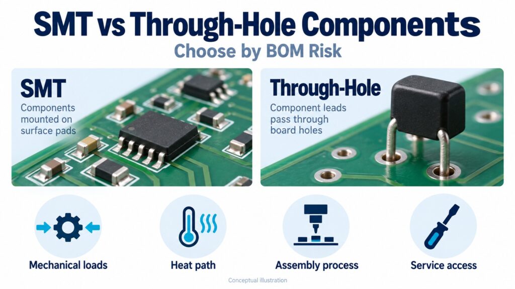
SMT mounts components on PCB surface pads; through-hole mounting places component leads through holes in the board. Choose between them by reviewing footprint, mechanical loads, electrical paths, heat flow and assembly requirements for each BOM item. A mixed design can meet different requirements on the same board.
SMT means surface-mount technology, while SMD means surface-mount device. THT means through-hole technology. These terms describe mounting; they do not, by themselves, establish a component's power rating, reliability or suitability for a production process.
For design and purchasing teams, the useful comparison is the approved package and assembly route for each BOM line.
SMT vs through-hole components at a glance
| Decision | Surface-mount components | Through-hole components |
|---|---|---|
| Board connection | Terminations connect to surface lands | Leads pass through board holes |
| Layout review | Check land pattern, underside pads and assembly clearance | Check lead geometry, finished holes and clearance on both sides |
| Mechanical loading | Review housing retention, attachment features and board strain | Review attachment features, lead support and board strain |
| Thermal design | Follow the specified package-to-PCB or package-to-heatsink path | Follow the specified lead, tab, case or heatsink path |
| Soldering | Often reflow; use the component's approved process | Wave, selective or hand soldering; qualified THR parts may use reflow |
| Inspection and repair | Access depends on package geometry and joint visibility | Access depends on lead layout, hole geometry and the board's thermal mass |
The useful comparison is a complete design and manufacturing route. A small footprint can be attractive while hiding an inspection requirement; a larger leaded part can be accessible while creating a difficult desoldering operation. Document the constraints before ordering alternatives.
How should you choose a mounting style for each BOM item?
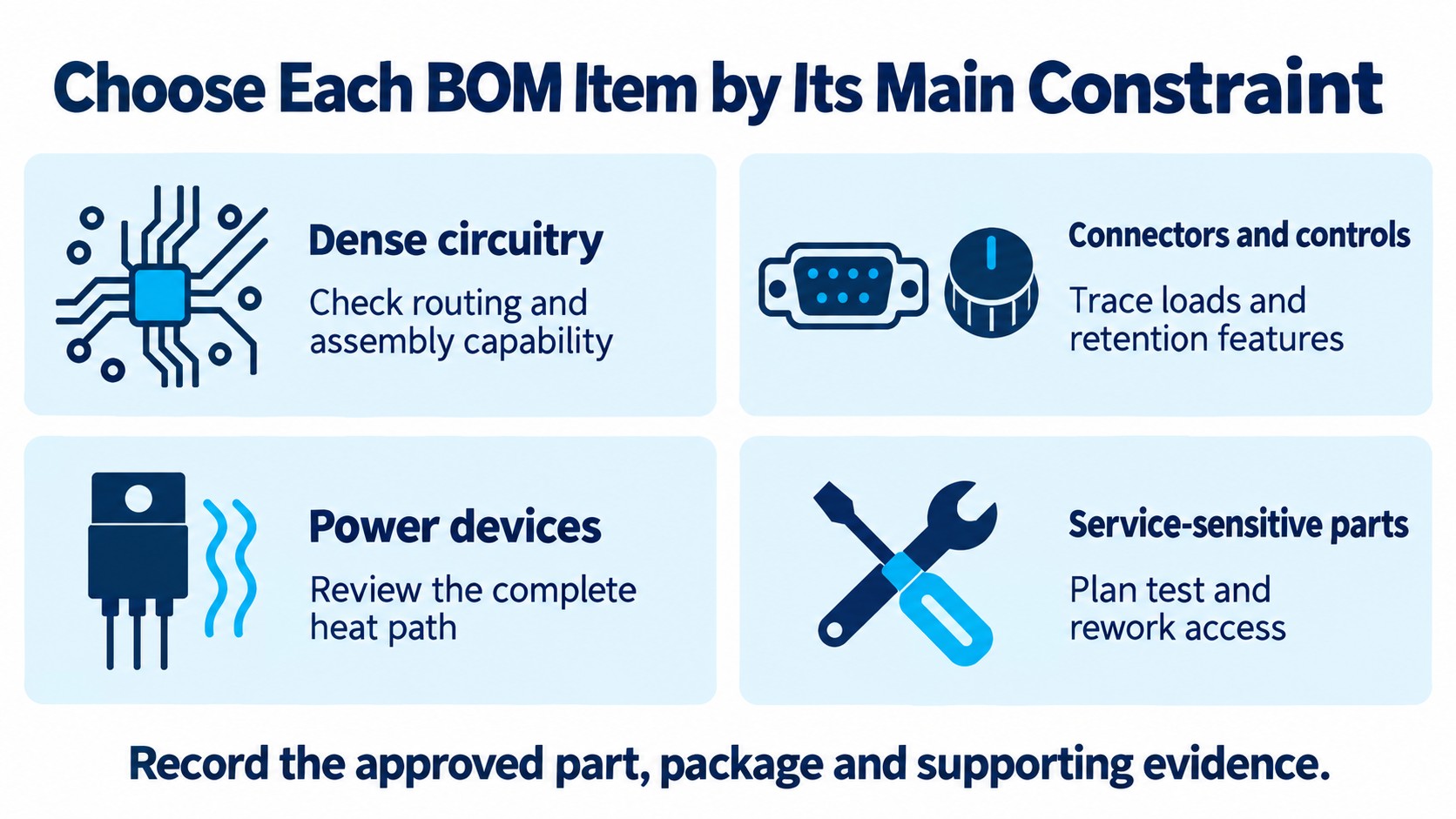
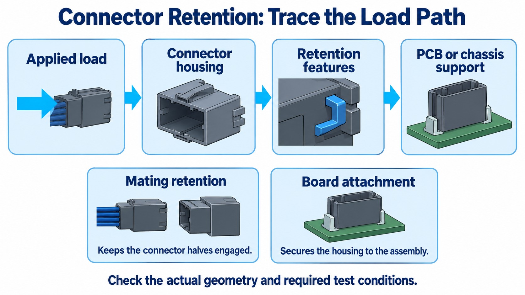
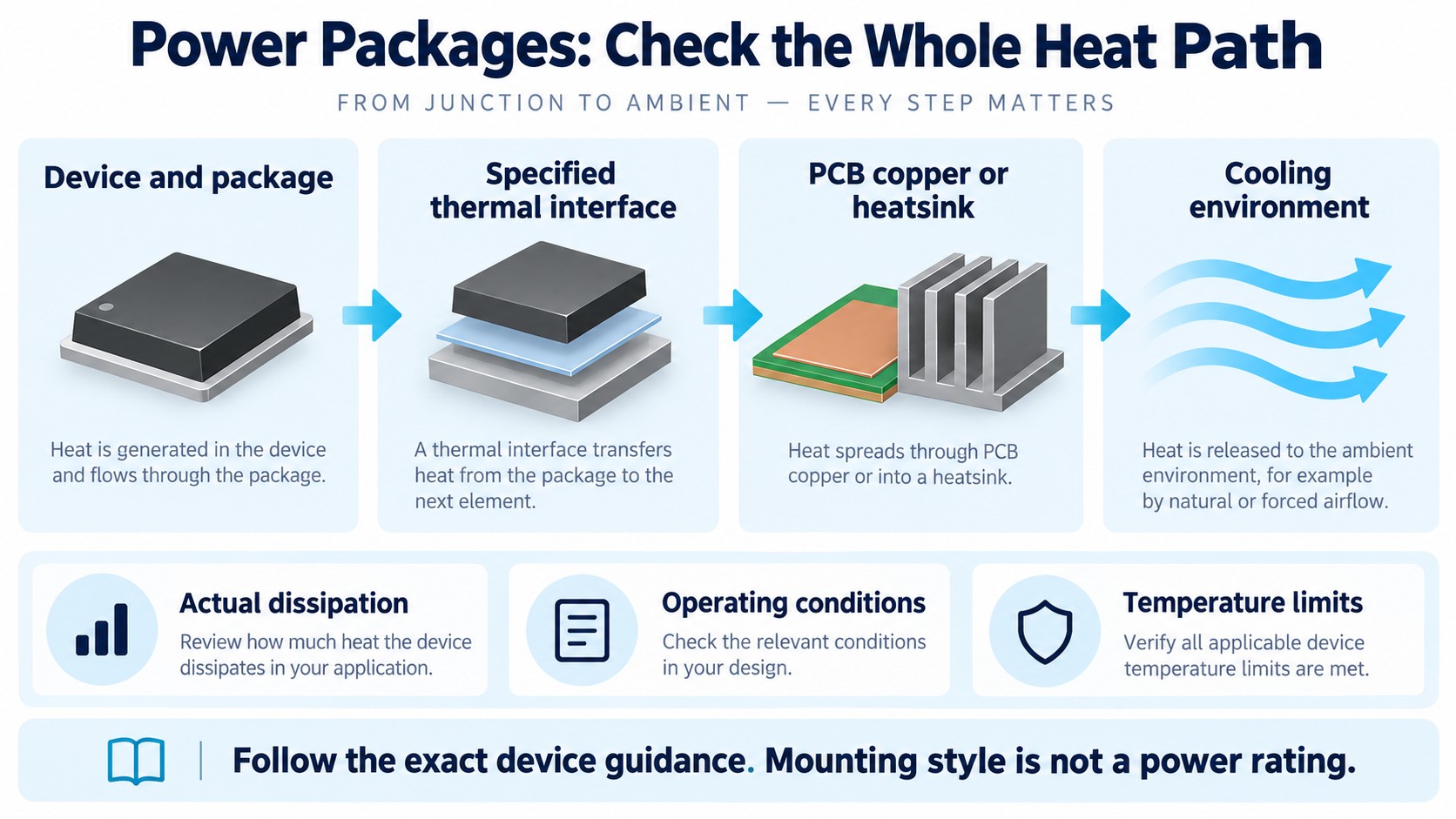
Start with the requirement that is hardest to change after layout. For a cable connector, that may be retention and the direction of applied force. For a power device, it may be the cooling arrangement. For dense logic, package availability, escape routing and assembly capability may dominate.
Use the following decision record before approving a component. It is a review framework, not a claim that every device in a category needs one mounting style.
| BOM position | First question | Evidence to attach to the choice |
|---|---|---|
| Dense logic, memory or small passives | Can the selected package be routed, assembled and inspected? | Package drawing, land pattern and assembly capability review |
| Connector or user-operated control | Where do insertion, extraction and cable forces go? | Retention design, board support and the required mechanical test conditions |
| Power conversion or switching device | How does heat reach the intended cooling system? | Package-specific thermal guidance and the actual load/cooling assumptions |
| Service-sensitive component | Can it be tested and replaced using the intended equipment? | Test access, rework clearance and a board-level service procedure |
Record the limiting requirement alongside the approved part number. That gives procurement a useful boundary: an alternative must satisfy that requirement as well as the electrical function. Changing an assembly method or thermal interface is an engineering change, even when the nominal electrical values appear similar.
Does through-hole mounting always give a stronger connector?
Connector reliability depends on the complete retention structure and its load path. Inspect the signal terminations, mechanical hold-downs, housing, mounting holes and board support separately. A mating latch keeps connector halves together; it does not automatically secure the connector body to the PCB.
Samtec's guidance on rugged connector design describes solder reinforcement in both surface-mount and through-hole forms, along with screw-down options. That is a practical reason to compare the actual attachment features rather than rank every connector by SMT or THT alone.
For a board-edge interface, trace a cable pull or mating force from the plug through the connector into its retention features and the supporting structure. Record the force direction, repeated-use requirement and board mounting arrangement. Where vibration, shock or thermal cycling matters, qualify the selected assembly under the applicable product requirements; the mounting label is insufficient evidence of passing those conditions.
Browse the connectors and interconnects category with those retention and interface requirements in hand. A catalog mounting-style filter narrows candidates, while the manufacturer's drawings establish the design details.
Can SMT handle high current and demanding thermal conditions?
Surface mounting does not mean low power. A package's thermal construction and the board or heatsink connected to it matter more than a broad mounting category. Review the exact device's electrical limits and thermal guidance at the intended operating point.
Infineon's TOLT application note documents a surface-mount power package with top-side cooling for high-current applications. Its thermal interface and heatsink arrangement are part of the design. This is a concrete counterexample to the assumption that high-current devices must have through-hole leads.
For a different heat path, TI's PowerPAD guidance explains how an exposed pad, its solder connection and the PCB thermal structure work together. Do not leave the pad unconnected because the signal leads look sufficient, and do not assume every exposed pad has the same electrical connection: use the exact device's instructions.
Compare thermal systems, not isolated headline ratings
Write down the expected dissipation, ambient conditions, copper or heatsink arrangement, and temperature limit used in the review. A rating obtained with a particular test board or cooling setup is not automatically available in a smaller enclosure or a different PCB layout.
When considering a substitute, compare where the heat leaves each package. A top-cooled device, a bottom thermal pad and a leaded device with a tab can require different mechanical and assembly provisions. Our power-module BOM review gives another example of keeping package details and operating conditions attached to a purchasing decision.
Is there a fixed frequency limit for through-hole components?
There is no useful universal clock-frequency cutoff that separates all SMT and through-hole parts. Evaluate the actual interconnect, signal edge behavior, return path and allowed signal degradation. A nominal clock rate alone does not describe the complete channel.
Shorter connections can help control parasitic effects, but mounting style does not specify the full path through a package, footprint, connector and PCB. Samtec's through-hole header information illustrates the distinction by providing performance information tied to a defined channel arrangement. Such evidence applies to that arrangement; it is not a blanket rating for all through-hole headers.
For a proposed package change, review the pin assignment, footprint and routing assumptions together. Carry the relevant signal-integrity requirement into the substitution review instead of using a generic “above this MHz, use SMT” rule.
Can SMT and through-hole components share one assembly flow?
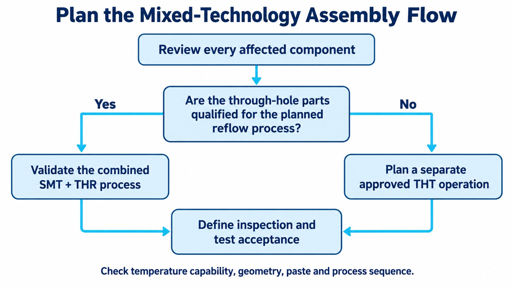
A mixed BOM needs a planned sequence, and some qualified through-hole parts can participate in reflow. Through-hole reflow, often called THR or pin-in-paste, uses an approved part and process combination. The fact that a part has leads does not establish whether its body can tolerate that process.
Würth Elektronik's ANP078a guide describes integrating THR components with SMT assembly. It identifies practical constraints including component temperature capability, pin and board geometry, solder-paste quantity and stencil design. Check those conditions before putting a conventional through-hole component on a reflow BOM.
If a candidate is not approved for the planned reflow process, determine the appropriate separate soldering operation with the assembler. The decision should be explicit in the manufacturing review rather than left to a purchasing description such as “through-hole connector.”
| Assembly question | Why it belongs in the BOM review |
|---|---|
| Which components see each heating operation? | A mixed board needs a compatible sequence for all affected parts |
| Which leads, holes and paste deposits form the joints? | A common electrical function does not guarantee process compatibility |
| Are fixtures or protected areas required? | Tool access and nearby parts can affect the chosen operation |
| What inspection follows each operation? | Identify how the process will be accepted before release |
Reflow classification is not a ready-made oven recipe
TI's moisture-sensitivity and soldering guidance distinguishes qualification conditions from an actual assembly profile. The production process must accommodate the component requirements and solder paste. The document also identifies selected package families that can use wave soldering under the stated conditions, reinforcing the need to follow the part's guidance.
For applicable moisture-sensitive devices, keep the specified moisture sensitivity level (MSL), packing and handling information with the manufacturing documentation. Neither “SMD” nor a temperature printed in an unrelated package example supplies the missing process instructions.
What changes in inspection, testing and rework?
Choose an inspection and repair method that can reach the relevant joints. A package with visible leads presents a different inspection problem from one with bottom terminations. Electrical testing, visual inspection and process qualification answer different questions; define which evidence is needed for acceptance.
TI's QFN/SON assembly guidance discusses X-ray inspection for process confirmation and monitoring. Its rework guidance also addresses heating, protection of adjacent devices and tool access. This does not mean every SMT joint requires the same inspection method or that every board needs identical X-ray coverage.
Avoid the opposite assumption that every through-hole part is easy to replace. Before assigning a field-service requirement, review access to both sides, nearby hardware, the soldered connections and the method for removing the component without damaging the board. A suitable connector or replaceable subassembly may be a better service strategy than repeatedly desoldering a densely populated board.
Include test access and rework clearance while selecting the package. Discovering that the required tool cannot reach a component after enclosure release turns an otherwise suitable electrical choice into a maintenance problem.
What should the purchasing team receive before requesting a quote?
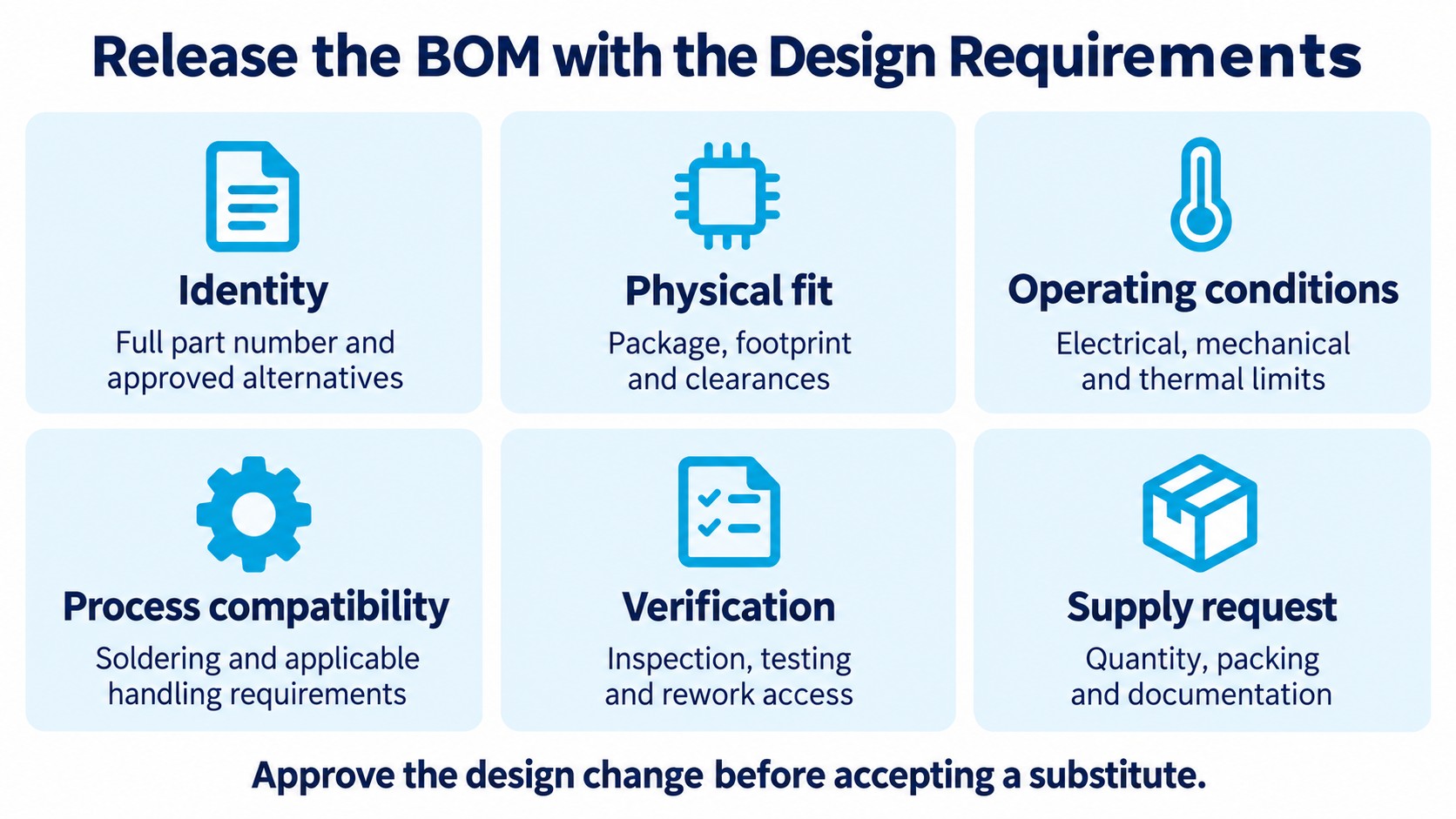
Release a complete component and process requirement, not just “SMT equivalent” or “through-hole version.” The approved manufacturer part number, package and drawing revision should identify the item being sourced. Any allowed alternative needs an explicit engineering review of the changed connections, loads and process.
Use this checklist as a handoff between engineering, manufacturing and procurement:
- Identity: full manufacturer part number, approved alternatives and relevant drawing or data-sheet revision.
- Physical fit: package, land pattern or hole requirements, orientation, height and assembly access.
- Operating conditions: electrical limits, mechanical loads and the intended thermal path.
- Process compatibility: approved soldering route and applicable moisture-handling or storage requirements.
- Verification: inspection, test and rework requirements that the completed assembly must meet.
- Supply request: quantity, packing preference and required documentation for the actual quotation.
Which mounting style costs less to build?
Compare total implementation cost using the real BOM and process route. Component price, PCB area, insertion or placement work, extra operations, fixtures, inspection and rework provisions may all affect the quote. A fixed batch-size threshold or universal cost-saving percentage cannot substitute for that review.
Send your BOM and component requirements for an RFQ with the approved package and any substitution constraints. Confirm availability, packing, price and delivery against that specific request.
Frequently asked questions
What is the difference between SMT and SMD?
SMT is the mounting technology; SMD describes a device intended for surface mounting. THT describes through-hole mounting. Use the exact manufacturer's package and assembly guidance when selecting or replacing the device.
Are through-hole components always more reliable?
No. Reliability depends on the complete component, attachment structure, PCB support, environment and qualified assembly process. For a connector, review signal terminations and mechanical retention separately, then test the intended load conditions.
Can through-hole parts go through a reflow oven?
Qualified THR or pin-in-paste parts can, when their temperature capability, geometry and solder process are compatible. Do not assume an ordinary through-hole component is reflow-compatible without the manufacturer's approval and a validated process.
Is SMT unsuitable for high-power circuits?
No. Surface-mount power packages can use PCB-based or top-side cooling paths. Assess the exact device, thermal interface and cooling arrangement rather than treating the mounting style as a power rating.
Can I replace a through-hole part with an SMD equivalent?
A matching electrical function is only the beginning. Check pin assignment, footprint, ratings under the intended conditions, heat flow, mechanical support and assembly requirements. Approve the design change before treating the new part as an accepted alternative.
Reviewed October 13, 2026 using the linked manufacturer application notes and connector guidance. The decision tables are engineering review frameworks; illustrations are conceptual and do not represent measured test results.