
EEPROM vs Flash Memory: the short answer
EEPROM and Flash are both non-volatile memory, but they suit different update patterns. The practical choice is not “which technology is better?” It is whether the system can safely tolerate the target device’s erase unit, write sequence, busy time, protection scheme, endurance rating, and power-loss recovery behavior. Those values are part-number-specific.
Quick comparison: EEPROM and Flash
| Selection question | Serial EEPROM | NOR Flash memory |
|---|---|---|
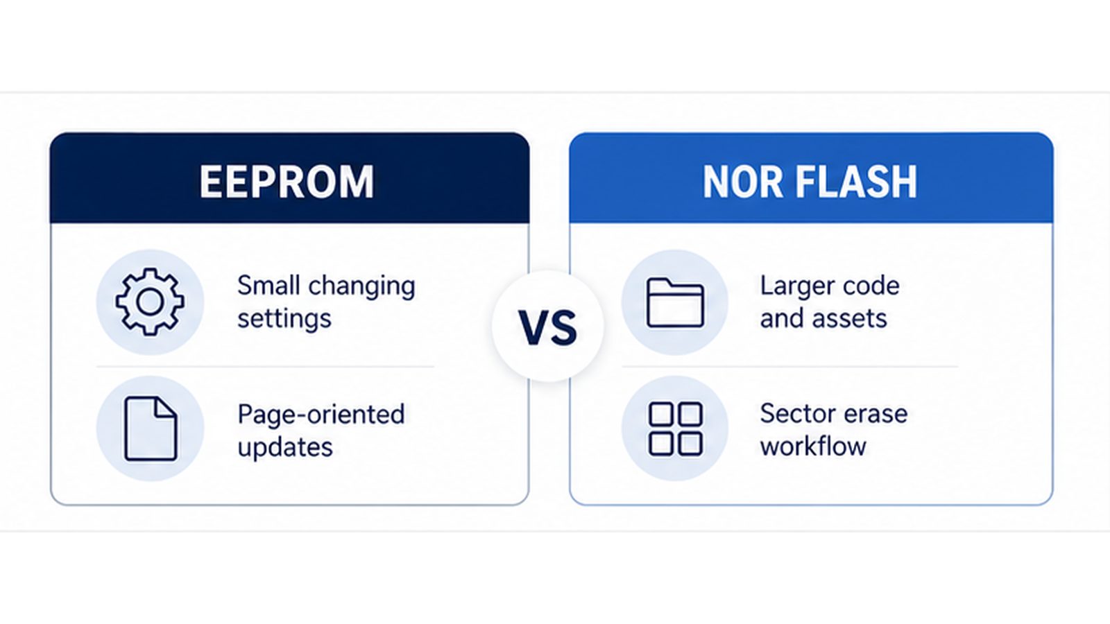
| What changes? | Small parameters and records | Firmware, assets, larger data regions |
| Typical update model | Byte or page-oriented writes, depending on the part | Page program plus sector, block, or chip erase |
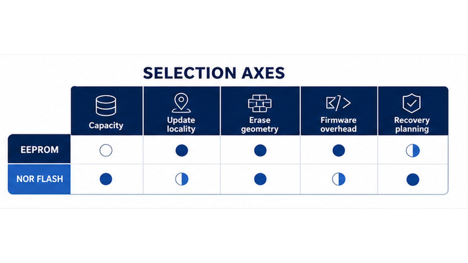
| Firmware implication | Address/page handling and write-cycle polling | Erase map, page boundaries, busy polling and recovery plan |
| Capacity direction | Commonly selected for smaller persistent data stores | Commonly selected when a larger non-volatile store is needed |
| Main buyer check | Interface, page size, write protection, endurance | Protocol mode, erase geometry, density, boot behavior, endurance |
How the update model changes the design
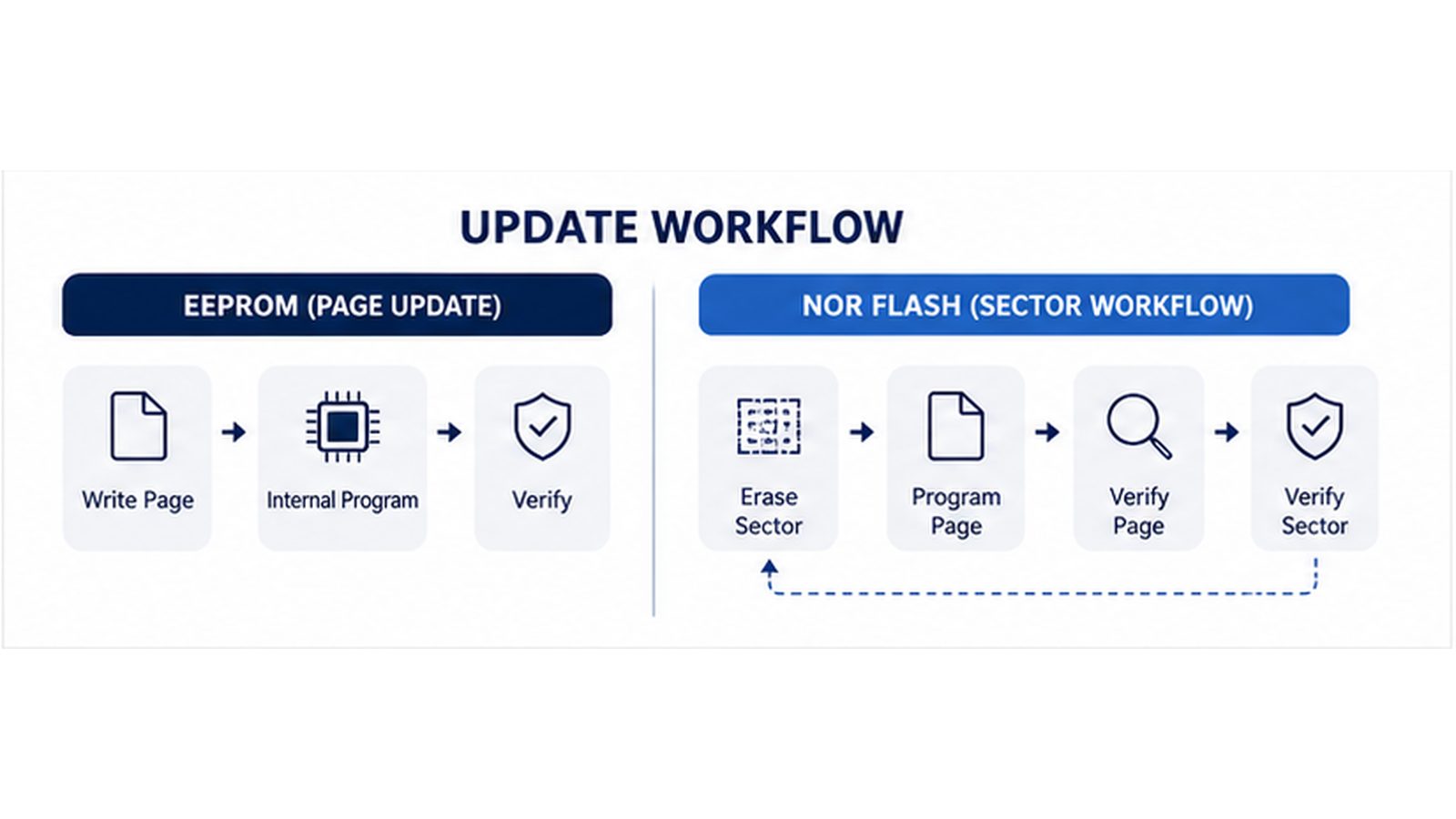
Many serial EEPROM devices expose byte-write or page-write behavior. Microchip’s EEPROM endurance material uses both byte-write and page-write devices as examples, while ST’s serial EEPROM portfolio describes page-oriented data management. This can make EEPROM a natural fit for settings that change independently, but the page size, write-cycle time, protection commands, and write endurance must still be checked for the exact device.
NOR Flash usually programs data in pages and erases a larger area. Microchip’s SFDP documentation describes page-boundary writes and sector, bulk, and chip erase operations for compatible NOR Flash. Infineon likewise explains that a NOR Flash erase applies to a whole sector or the whole array rather than only one portion of a sector. That erase geometry affects data layout, wear management, and what the application must recover after an interrupted update.
Erase granularity: the point most designs miss
If a machine stores one calibration constant every few hours, replacing a single byte or page can be easier to reason about than recycling an entire Flash sector. If a controller stores firmware images or large configuration bundles, a sector-based update can be the sensible trade-off.
Capacity, speed, endurance and retention: compare the right values
Capacity, read rate, program time, erase time, endurance, retention, voltage range, and temperature range all vary by family and orderable part number. For example, Microchip and ST publish high endurance and long retention figures for particular serial EEPROM portfolios; those figures cannot be carried over as a blanket EEPROM specification. The same caution applies to Flash frequency and sector size.
- Estimate bytes written per event, events per day, and the specific memory locations affected.
- Identify the smallest safe erase unit and space needed for metadata, rollback, or wear leveling.
- Check whether reads must continue while an erase/program operation is active.
- Define brownout handling, write protection, checksum/CRC, and a valid-record strategy.
- Verify the data sheet at the actual voltage, temperature, clocking mode, and package option.
Application mapping for B2B component selection
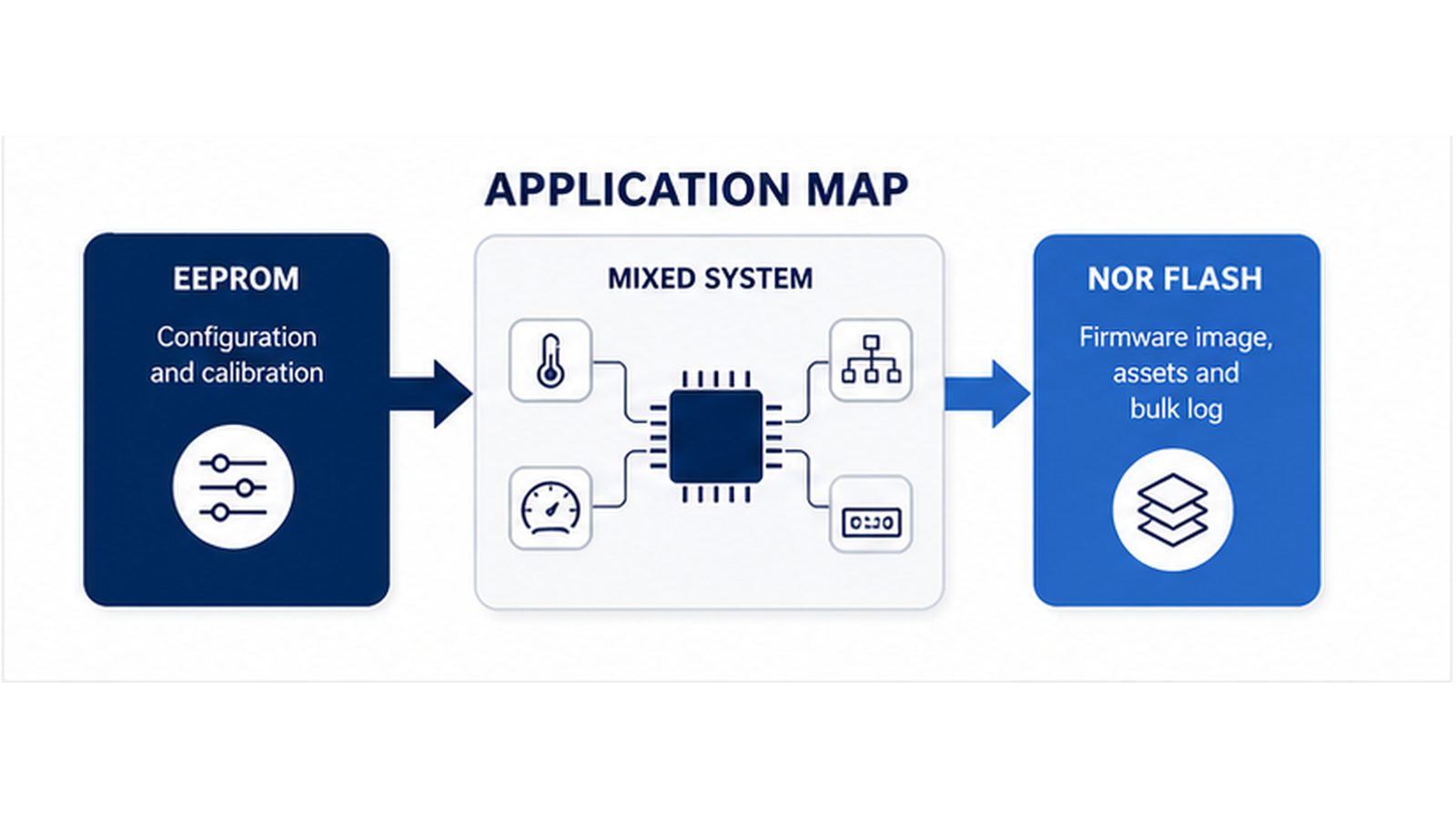
Serial EEPROM is often evaluated for device identity, configuration, calibration, threshold data, manufacturing parameters, and small logs. NOR Flash is often evaluated for boot code, field-updateable firmware, display assets, lookup tables, or larger log partitions. A mixed system can use both: EEPROM for frequently changed small records and Flash for bulk code or content.
For serial EEPROM examples, an RFQ can begin with the original part number and interface family, such as 24LC512T-I/SN, M24C64-FMC6TG, or M95512-DFMC6TG. These links are starting points for identification, not a compatibility declaration. For broader family navigation, see the EEPROM Memory ICs hub.
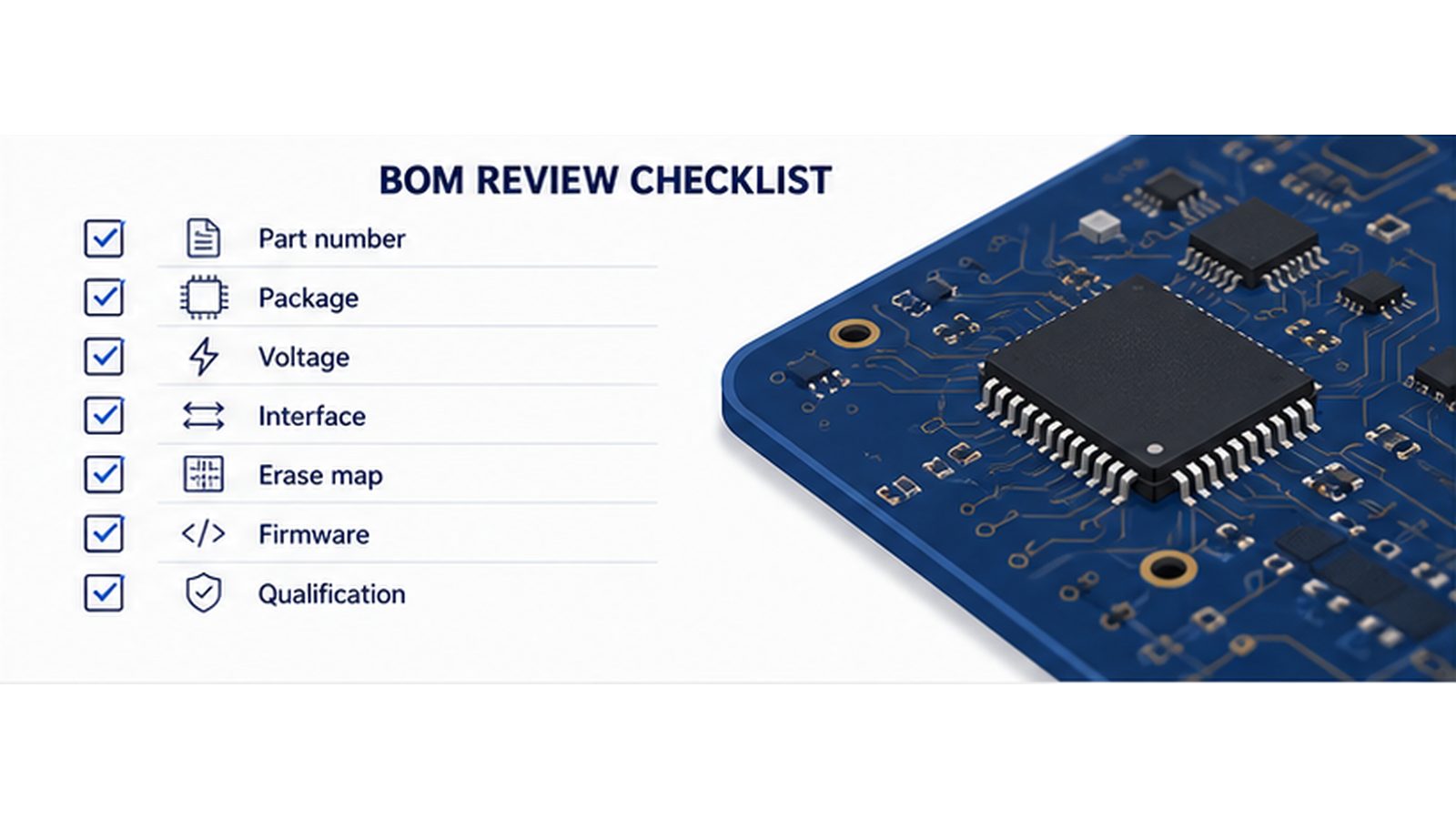
EEPROM vs Flash memory selection checklist
- Full manufacturer part number, package, and package suffix.
- Memory type, density, organization, page size, and—where applicable—sector/block map.
- Interface and electrical requirements: I2C/SPI/QSPI mode, voltage range, frequency, pins, and pull-up or routing needs.
- Program/erase timing, busy behavior, protection features, and power-loss recovery requirements.
- Endurance and retention conditions at the intended temperature and voltage.
- Firmware assumptions: boot method, address width, command set, IDs, status bits, and error handling.
- Approved-alternative rules, quantity, required date, traceability/compliance documents, and customer qualification constraints.
Can EEPROM and Flash be substituted?
Do not treat EEPROM and Flash as substitutes merely because both retain data without power. A replacement review must confirm memory architecture, density, pinout, supply limits, interface commands, timing, erase model, protection behavior, package, firmware support, lifecycle status, and qualification rules. A memory IC can fit the same board footprint yet still fail the system’s update flow.
If the original BOM allows alternatives, submit the complete part number and system requirements for engineering and quote-time verification. Avoid approving a substitute from package or capacity alone.
Frequently asked questions
Is Flash memory a type of EEPROM?
Flash is commonly described as a form of electrically erasable non-volatile memory, but the selection decision remains practical: Flash normally organizes erase operations by sector/block/chip, while serial EEPROM is often chosen for small-data byte/page update behavior. Confirm the target device’s data sheet.
Is EEPROM better than Flash for configuration data?
EEPROM can be a strong fit when only a small amount of configuration data changes independently and often. Flash can also store configuration data when firmware handles sector erase, record layout, and recovery correctly. The best choice depends on write frequency, data size, and the failure model.
Does higher clock speed decide the choice?
No. Clock speed is only one interface parameter. Check write-cycle/erase timing, page size, density, endurance, retention, voltage, package, temperature, protection features, lifecycle, and sourcing constraints together.
Need help reviewing an EEPROM or Flash BOM?
Send the original manufacturer part number, package, quantity, target voltage, operating temperature, application, required date, and approved-alternative rules through the ApexComponent inquiry form. Current stock, price, lead time, compliance documents, and replacement suitability require quote-time verification.