
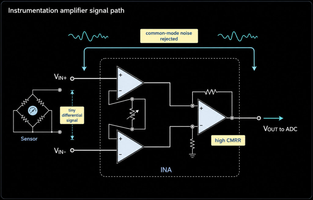
An instrumentation amplifier is a precision amplifier for small differential signals. It is often used when a sensor gives only a few millivolts, but the circuit also has noise or a large common-mode voltage. A good instrumentation amplifier gives high input impedance, high common-mode rejection ratio (CMRR), and accurate gain. This makes it useful for strain gauges, load cells, pressure bridges, RTD front ends, ECG inputs, and some current-shunt measurements.
The main buying decision is simple: use a discrete op amp circuit only when the accuracy need is modest or the design is for learning. Use a dedicated instrumentation amplifier IC when you need stable CMRR, low offset, low drift, small size, matched internal resistors, and a known gain equation. For purchase, stock, price, lead time, package, lifecycle, and compliance must be verified by RFQ or BOM review.
What Is an Instrumentation Amplifier?
An instrumentation amplifier, often shortened to INA or in-amp, amplifies the voltage difference between two input pins. At the same time, it rejects the voltage that is common to both inputs. That shared voltage is called common-mode voltage.
This is different from a basic A differential amplifier explains the subtractor idea and resistor-ratio matching. An instrumentation amplifier adds input buffer stages and precision matching so the circuit can measure weak sensor signals without loading the sensor. For a detailed explanation of subtractor circuits, see our Differential Amplifier guide.
In plain terms:
| Feature | What it means | Why it matters |
|---|---|---|
| Differential input | Measures VIN+ minus VIN- | Useful for bridge sensors and shunt voltage |
| High input impedance | Draws very little current from the signal source | Protects weak or high-resistance sensors from loading error |
| High CMRR | Rejects voltage or noise that appears on both inputs | Helps measure small signals in noisy systems |
| Gain resistor | One resistor can set gain in many INA ICs | Makes gain easier to design and adjust |
| Reference pin | Sets the output baseline | Useful for single-supply ADC inputs |
How an Op Amp Instrumentation Amplifier Works
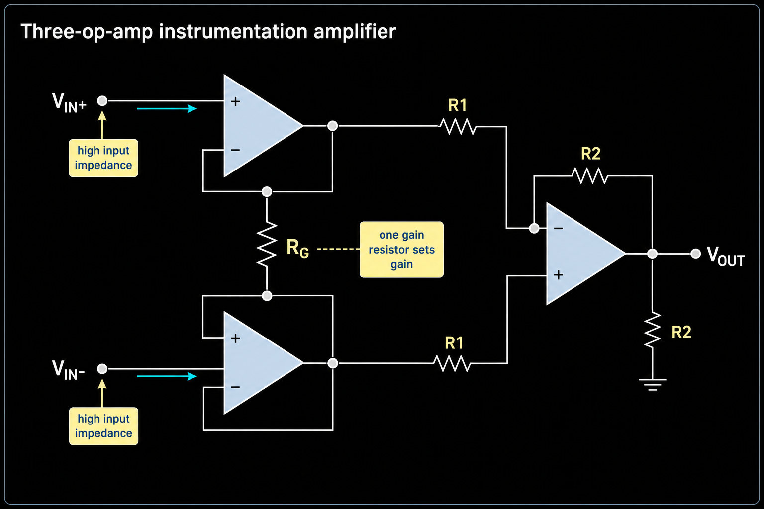
The common teaching circuit uses three op amps. The first two op amps act as input buffers and gain stages. The third op amp acts as the subtractor. This structure keeps the input impedance high while converting the differential signal into a single-ended output.
Many textbook versions use one gain resistor, often called RG. Reducing RG increases gain. The exact gain equation depends on the resistor network or IC, so do not copy one formula across all parts. For example, TI's INA333 uses G = 1 + (100 kohm / RG), while Analog Devices' AD620 uses a different constant in its gain equation. Always use the selected IC data sheet.
Design impact:
| Design item | Check before release |
|---|---|
| Gain | Confirm output will not saturate at sensor maximum and minimum |
| Input common-mode range | Confirm both inputs stay inside the allowed range at the chosen supply |
| Output swing | Confirm the output reaches the ADC input range with margin |
| RG tolerance and drift | Include the external resistor error in total gain error |
| REF pin drive | Drive the REF pin from a low-impedance source when shifting output level |
Why High CMRR Matters
CMRR tells you how well the amplifier rejects common-mode voltage. In a sensor bridge, both input wires can move together because of excitation voltage, cable pickup, ground shift, or EMI. The useful signal can be tiny compared with that shared voltage.
High CMRR is not a marketing detail. If the common-mode rejection is weak, part of the common-mode voltage becomes output error. TI's current-sense application note shows that higher common-mode voltage can create large measurement error when CMR is not strong enough. This is one reason current-shunt and sensor designs should check CMRR at the real common-mode voltage, temperature, gain, and frequency.
For procurement, ask for the exact operating condition. A part may show good CMRR at one gain or one frequency but perform differently at another gain or in a PWM system.
Why High Input Impedance Matters
Many sensors cannot drive a heavy load. A strain gauge bridge, pressure sensor, thermocouple front end, or high-resistance biomedical electrode can be affected if the amplifier input draws too much current. High input impedance keeps the measurement closer to the real sensor voltage.
Dedicated instrumentation amplifiers often specify very high differential and common-mode input impedance. For example, TI's INA333 data sheet lists input impedance in the Gohm range, and ADI's AD620 data sheet also lists Gohm-level input impedance. That does not mean every INA is right for every sensor. You still need to check input bias current, input offset current, source resistance, leakage path, filtering, and PCB contamination risk.
Sensor Bridge and Load Cell Use
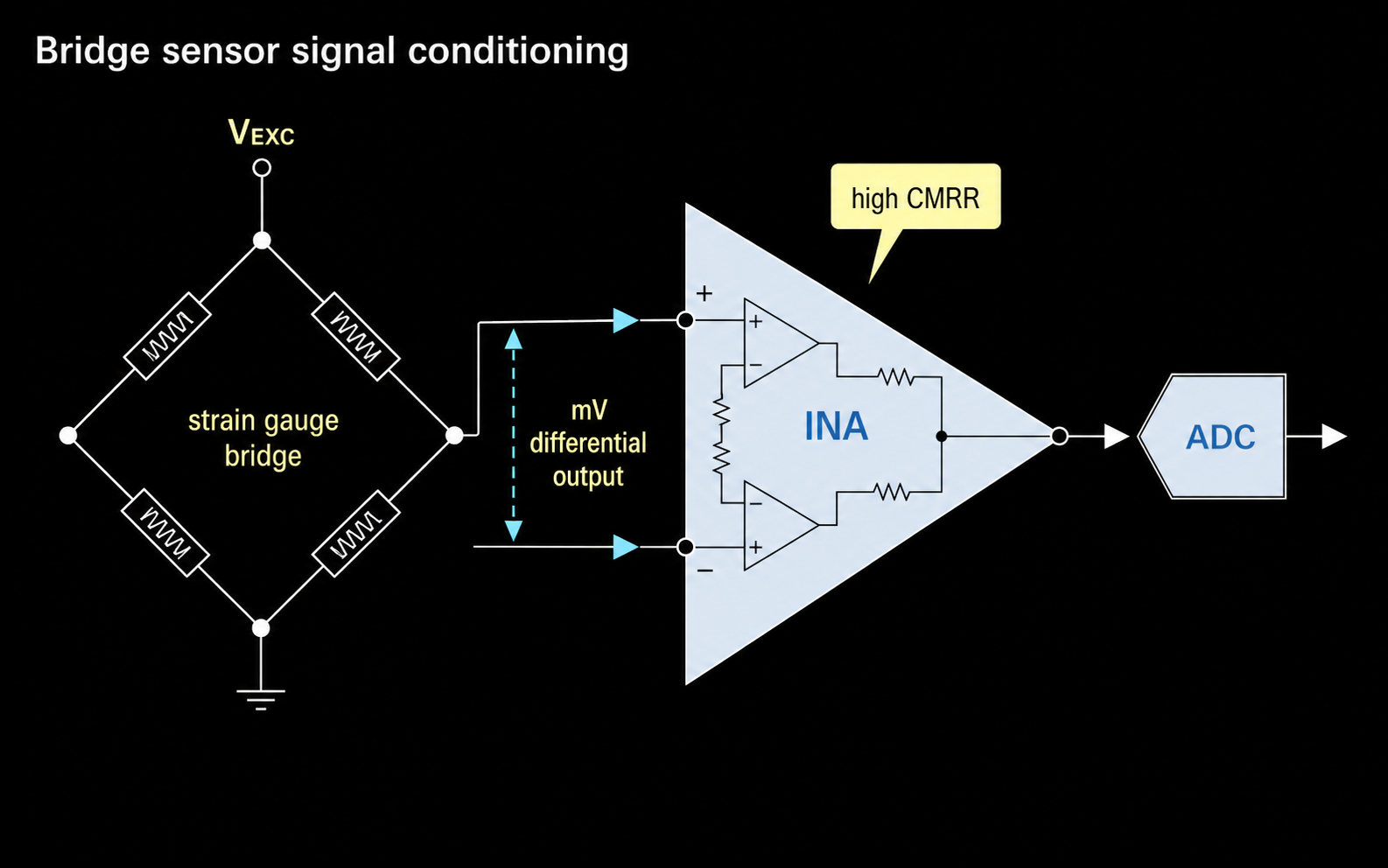
Instrumentation amplifiers are a strong fit for bridge sensors because a bridge often produces a small differential output around a larger common-mode level. Common examples include:
| Application | Why an instrumentation amplifier helps | RFQ/BOM check |
|---|---|---|
| Strain gauge bridge | Amplifies millivolt-level bridge output | Gain, offset drift, noise, bridge excitation, package |
| Load cell | Measures small changes from weight | Low drift, CMRR, input bias current, ADC range |
| Pressure bridge | Reads small pressure-sensor output | Supply voltage, input range, calibration plan |
| RTD or thermocouple front end | Conditions low-level sensor signal | Cold-junction or excitation method, noise, offset |
For a bridge sensor, do not select by gain alone. Check bridge excitation, common-mode voltage, expected sensor span, zero offset, input filtering, and calibration. A low-noise, zero-drift INA may be better when the sensor output changes slowly and accuracy matters.
Current Shunt Use
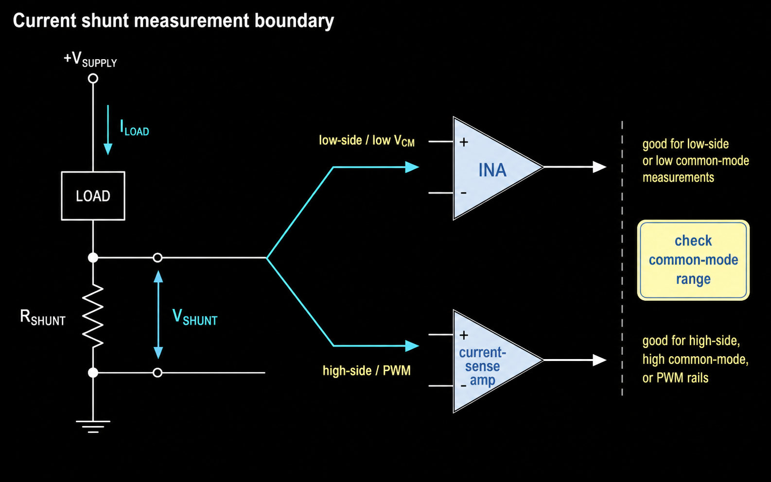
A current shunt creates a small voltage that is proportional to current. An instrumentation amplifier can measure this small differential voltage when the common-mode voltage is inside the amplifier input range. This can work for low-side current sensing or lower-voltage high-side sensing.
For high-side current sensing on 24 V, 48 V, motor, battery, or fast-switching rails, a dedicated current-sense amplifier is often better. Current-sense amplifiers are built for wider common-mode input voltage, faster response, PWM rejection, and current measurement fault cases. TI's high-side motor current monitoring note gives examples where current-sense or difference amplifiers become the better choice as voltage and error requirements rise.
Use this rule:
| Current-shunt case | Better starting point |
|---|---|
| Low-side shunt, low voltage, slow signal | Instrumentation amplifier can be considered |
| Sensor-like shunt voltage with high accuracy need | Precision INA or zero-drift INA |
| High-side shunt on 24 V, 48 V, or motor rail | Dedicated current-sense amplifier |
| PWM or fast fault detection | Current-sense amplifier with suitable bandwidth and common-mode behavior |
| Isolated high voltage | Isolated current sensor or isolated amplifier |
Dedicated Instrumentation Amplifier IC vs Discrete Op Amp Circuit
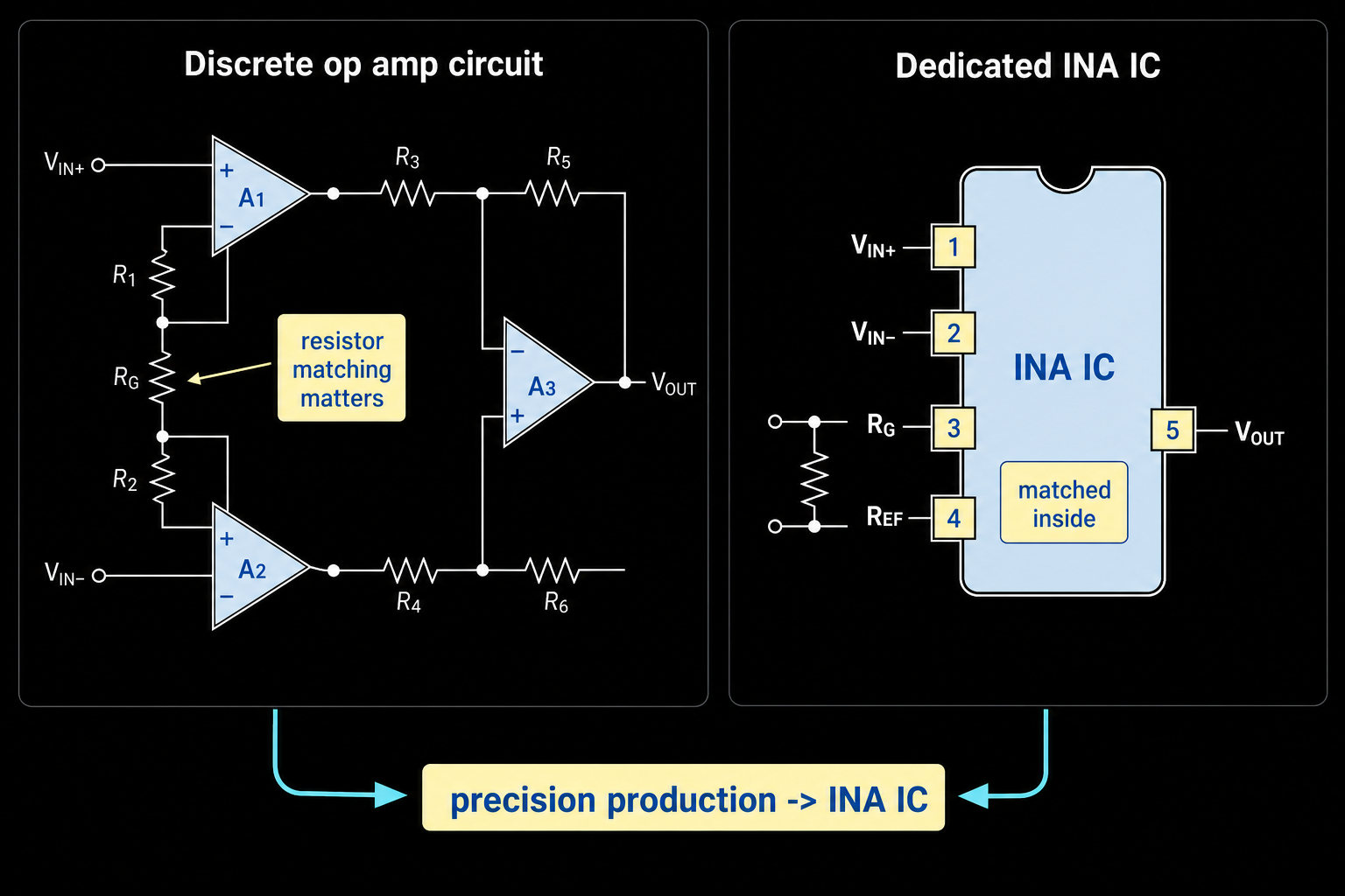
A discrete op amp instrumentation amplifier can teach the circuit and may work in a low-precision design. But high CMRR depends on resistor matching, layout symmetry, input filtering, and temperature behavior. Small mismatch can reduce real-world rejection.
A dedicated instrumentation amplifier IC is usually better when:
| Need | Why a dedicated INA IC helps |
|---|---|
| High CMRR | Internal resistor matching and trim improve rejection |
| Low offset and drift | Precision ICs control DC error over temperature |
| One-resistor gain | Gain is easier to set and document |
| Small PCB area | One IC replaces several op amps and matched resistors |
| Low power | Many INAs are designed for portable sensor systems |
| Known input protection | Some ICs include input filtering or overvoltage protection |
| Production sourcing | Part number, package, and data sheet specs are easier to control |
Use a discrete circuit only when the design has enough error budget, the common-mode voltage is easy, and the resistor network can be controlled. For production sensor equipment, a dedicated IC is usually the safer starting point.
Common Selection Mistakes
| Mistake | Risk | Better action |
|---|---|---|
| Treating an INA as just a stronger op amp | Wrong input range or output swing | Check the full input/output range at your supply |
| Copying a gain formula from another IC | Wrong gain and saturated output | Use the selected data sheet gain equation |
| Ignoring common-mode voltage | Large measurement error or invalid operation | Check CMRR and input range under real conditions |
| Using a generic INA for any shunt | Poor high-side or PWM current result | Compare with current-sense amplifiers |
| Buying by stock only | Wrong package, grade, or lifecycle | Verify ordering code, package, lifecycle, and compliance by RFQ |
How to Choose an Instrumentation Amplifier
Use this short checklist before you send the BOM:
- Define the sensor signal: minimum, maximum, offset, frequency, and source resistance.
- Define common-mode voltage at both inputs, not only the differential signal.
- Choose gain so the output fits the ADC range with headroom.
- Check CMRR at gain, frequency, temperature, and common-mode voltage close to your design.
- Check input bias current, offset voltage, offset drift, and noise.
- Check supply voltage, output swing, REF pin drive, and startup behavior.
- Verify package, temperature grade, lifecycle, compliance, stock, price, and lead time by RFQ or uploaded BOM.
FAQ
What is an instrumentation amplifier used for?
It is used to amplify small differential signals while rejecting common-mode noise. Common uses include strain gauges, load cells, pressure bridges, ECG inputs, RTD front ends, and some current-shunt measurements.
Is an instrumentation amplifier the same as a differential amplifier?
No. A differential amplifier is the basic subtractor idea. An instrumentation amplifier adds high-impedance input stages and precision matching, so it is better for weak sensor signals and high CMRR applications.
What does high CMRR mean in an instrumentation amplifier?
High CMRR means the amplifier rejects voltage that appears on both inputs. This is important when the sensor signal is small but the cable, bridge, or shunt has a larger common-mode voltage.
How does the gain resistor work?
Many instrumentation amplifier ICs use one external resistor, called RG, to set gain. The exact equation is different by device, so use the data sheet for the selected IC.
When is a dedicated instrumentation amplifier IC better?
Use a dedicated INA IC when you need high CMRR, low offset, low drift, compact layout, known gain accuracy, and repeatable production behavior. A discrete op amp circuit is better mainly for learning, low-cost experiments, or low-precision designs.
Can I use an instrumentation amplifier for current shunt sensing?
Yes, if the shunt voltage and common-mode voltage stay inside the amplifier limits. For high-side, high-voltage, PWM, or fast fault sensing, start with a dedicated current-sense amplifier instead.
Request Quote / Upload BOM
If your BOM includes instrumentation amplifier ICs, sensor bridge amplifiers, current-sense amplifiers, or precision op amps, submit the target part numbers and operating notes for review. Use Request Quote for known part numbers and Upload BOM when you need package, lifecycle, lead-time, or alternative-part checks across a full project list.
Internal Links
- Instrumentation Amplifier ICs
- Differential Amplifier Tutorial
- Operational Amplifiers
- Request Quote
- Upload BOM
External Sources
- Electronics Tutorials, "Instrumentation Amplifier": https://www.electronics-tutorials.ws/opamp/instrumentation-amplifier.html
- Texas Instruments, INA333 data sheet: https://www.ti.com/lit/gpn/INA333
- Texas Instruments, INA826 data sheet: https://www.ti.com/lit/gpn/INA826
- Analog Devices, AD620 data sheet: https://www.analog.com/media/en/technical-documentation/data-sheets/AD620.pdf
- Texas Instruments, "High-Side Motor Current Monitoring for Overcurrent Protection": https://www.ti.com/lit/an/sboa163a/sboa163a.pdf