Table of Contents
What Is a PMIC? Power Management Integrated Circuits
Your microcontroller needs 3.3 volts. The memory chip wants 1.2V. The motor driver expects 12V. The sensors run on 1.8V, and the wireless module won’t turn on below 2.5V.
That’s five different voltages. One way to handle it: put five separate voltage regulators on the board, wire up five power lines, and manage the order in which each one turns on. Lots of designs work this way.
But by the time you hit the third voltage, the parts list is getting long. The circuit board is running out of space. And you start asking: is there one chip that does all of this?
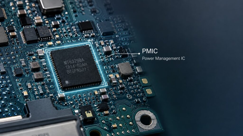
Yes. It’s called a PMIC — short for Power Management Integrated Circuit. The name sounds technical, but the idea is simple: one chip, many voltages. Here’s what that actually means and when it’s worth using.
1. What Is a PMIC?
A PMIC is a single chip that handles multiple power jobs at once. Instead of putting five separate regulator chips on your board, you put one PMIC.
The best way to picture it: think of separate voltage regulators as buying tools one at a time — a screwdriver, a wrench, a pair of pliers. A PMIC is the Swiss Army knife. Same toolbox, fewer items to keep track of. And the tools inside are built to work together — the PMIC automatically turns things on in the right order, so you don’t have to design that yourself.
What’s Inside a Typical PMIC?
Most PMICs contain several types of power circuits on one chip:
Step-down converters (buck converters): These lower a voltage efficiently. If you put in 12V and need 3.3V for a processor, a buck converter does that while wasting very little power — usually 5 to 15 percent. These handle the high-current power rails.
LDOs (low-dropout regulators): These also lower voltage, but they do it more quietly — less electrical noise on the output. The trade-off is they waste more power as heat. LDOs are used for sensitive circuits like audio or radio where a clean power supply matters more than efficiency.
Step-up converters (boost converters): These raise a voltage. For example, taking 3.7V from a battery and boosting it to 5V for a USB port.
Power-up sequencer: This controls the order in which each voltage turns on. Some processors need core voltage before I/O voltage, and I/O before the peripherals. The PMIC handles this in hardware so the processor boots reliably.
Communication interface (I2C or SPI): This lets the main processor talk to the PMIC — to adjust voltages, check for problems, or change settings while the system is running.
Not every PMIC has all of these. A simple PMIC for a fitness tracker might have one buck converter, two LDOs, and a battery charger. A PMIC for a car’s engine computer might have six bucks, four LDOs, a step-up converter, voltage monitors, and a watchdog timer. The concept is the same — it just scales up or down depending on how complex the system is.
Why “Integration” Matters
The key difference between a PMIC and a regular voltage regulator chip is that a PMIC puts everything in one package. If you look at a PMIC’s internal diagram, you’re seeing what would normally be an entire page of a schematic — multiple regulator chips, each with its own supporting capacitors and resistors — squeezed into a single part. Fewer parts means a smaller board, a shorter parts list, and less to go wrong during assembly.
2. PMIC vs Separate Regulators — Which One Should You Use?
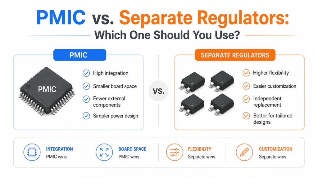
A PMIC isn’t always the right answer. Sometimes two or three separate LDOs are cheaper, simpler, and easier to buy. The question is: at what point does combining everything into one PMIC become the smarter choice?
Here’s a practical comparison:
Number of parts to buy: With separate regulators, you buy one regulator chip per voltage, plus capacitors and resistors for each one. With a PMIC, you buy one chip and fewer supporting parts overall.
Board space: Separate regulators take up roughly twice as much space each time you add a new voltage. A PMIC becomes more space-efficient once you need three or more voltages.
Design work: Each separate regulator must be chosen, tested, and validated on its own. A PMIC means more time reading the datasheet upfront, but less total testing since everything is already designed to work together inside the chip.
Flexibility: With separate regulators, you can change one voltage without touching the others. With a PMIC, all the voltages are tied to what that specific chip can do — you can’t swap one rail without changing the whole chip.
Cost: For one or two voltages, separate regulators are usually cheaper. Once you need four or more, a PMIC often costs less overall because you buy fewer parts and spend less on assembly.
Supply chain risk: If one separate regulator gets discontinued, you only need to replace that one part. If a PMIC gets discontinued, your entire power design needs to be redone — it’s a single point of failure.
Electrical noise: Separate regulators are naturally isolated from each other. In a PMIC, a sudden current spike on one voltage line can briefly affect the other lines on the same chip. This usually isn’t a problem, but it matters in noise-sensitive designs.
A Simple Rule of Thumb
1 or 2 voltages, low power, noise-sensitive: Use separate LDOs. Keep it simple.
3 to 5 voltages, mixed power levels, tight on board space: A PMIC starts to make sense. Reducing your parts list alone is often enough reason.
6 or more voltages, complex power-up sequencing, very limited board space: A PMIC is the standard answer. Managing six separate regulators with coordinated turn-on timing is a full design project by itself.
Battery-powered device that spends most of its time asleep: PMICs built for battery life (like Nordic’s nPM series or Maxim’s MAX776xx) often work better than separate regulators because the PMIC can coordinate sleep modes across all power lines — something separate chips can’t do.
What We’re Seeing as a Distributor
STMicroelectronics — one of the major chip makers — has publicly said that more and more customers are asking for integrated PMIC solutions to simplify their parts lists. The PMIC market as a whole is projected to reach about $30 billion in 2026, growing roughly 8% per year (Business Research Insights, June 2026).
From our side of the desk, we see the same trend. Multi-voltage PMICs are growing faster than the rest of the power management market, pushed by two big changes: the switch to DDR5 memory (which requires a PMIC on every memory module) and the fact that embedded systems keep getting more complex.
This doesn’t mean separate regulators are disappearing. We still ship thousands of 7805s and LM317s every month. But for new designs with three or more different voltages, the conversation increasingly starts with “which PMIC?” rather than “which regulators?”
3. Where Are PMICs Used in the Real World?
PMICs show up anywhere a device needs several different voltages in a small space. Here are the most common places you’ll find them.
Embedded Systems — Processor + PMIC
This is the classic PMIC use case. Take a processor like the STM32MP1 from STMicroelectronics. It needs 3.3V for its I/O pins, 1.8V for memory, 1.2V for the processor core, and sometimes 0.8V for a low-power sleep mode. That’s four voltages from a single chip.
ST makes a companion PMIC called the STPMIC1 that handles exactly this. You give it one input voltage (5V or 12V), and it provides all four outputs, plus it manages the power-up sequence so the processor boots correctly every time.
The same idea applies to FPGAs — programmable chips that often need five or more voltage rails, all turning on in a specific order. A PMIC built for FPGA power handles the sequencing, monitoring, and adjustment automatically, saving the designer from building that logic from scratch.
DDR5 Memory — PMICs Move onto the Memory Stick
DDR5 changed how computer memory gets its power. In the previous generation (DDR4), the motherboard provided the voltages to the memory slots through long copper traces. In DDR5, every memory stick has its own tiny PMIC right on the board.
Why the change? The longer the path between the voltage regulator and the chip it powers, the more the power quality degrades — think of it like water pressure dropping over a long hose. By putting the PMIC directly on the memory stick, millimeters from the memory chips, the power stays clean and stable.
This is now a requirement for all DDR5 memory — every DDR5 stick on the market has a PMIC. That’s created a whole new category of components for engineers and buyers to source.
Cars — PMICs in the Engine Computer
A modern car’s engine control unit (ECU) needs multiple voltages: the main processor at 3.3V or 1.8V, the communication chips (CAN and LIN) at 5V, and sensors at various analog voltages. All of this has to work from the car’s 12V battery — which, in reality, can dip as low as 6V during a cold start or spike to 40V when a heavy load switches off.
Automotive PMICs handle this by accepting a wide input range (typically 4V to 40V) and producing all the needed voltages on one chip. They also include safety features: built-in voltage monitoring that can reset the system if any power line goes out of spec — without waiting for the main processor to notice the problem.
Phones, Tablets, and Wearables
Every smartphone has at least one PMIC, and flagship phones often have three or four. The main PMIC handles the processor and memory power. A separate PMIC manages battery charging. Others might handle the display or camera modules.
For wearables like smartwatches, the biggest challenge is standby power. A smartwatch that’s worn 23 hours a day and only actively used for one needs its PMIC to draw almost no current while asleep — microamps, not milliamps. This has created a category of ultra-low-power PMICs designed specifically for battery life, where the entire chip uses less power in sleep mode than a single separate LDO would.
Energy Harvesting — Power from the Environment
Some IoT sensors don’t have batteries at all — they harvest energy from a tiny solar panel, a vibration source, or even radio waves. These energy sources are unpredictable: a solar panel in a warehouse might get light for two hours and darkness for twenty-two.
Energy-harvesting PMICs handle this by managing the unpredictable input, storing extra energy in a supercapacitor when it’s available, and making sure the sensor doesn’t try to draw more power than what’s been collected. They include special low-voltage startup circuits that can begin operating from just a few hundred millivolts — far below what a normal regulator needs.
4. How to Start Choosing a PMIC
Picking a PMIC is harder than picking a single regulator because you’re not choosing one voltage — you’re choosing a whole power system. Here are three questions to answer before you start searching through part catalogs.
Question 1: How Many Voltages Do You Actually Need?
This sounds obvious, but the most common mistake we see is underestimating how much current one voltage line really needs. A PMIC whose main output is rated for 2 amps will overheat and shut down if your processor briefly pulls 2.5 amps during a heavy computing burst.
Don’t look at the “typical” current number in your processor’s datasheet — that’s for steady operation. Look at the peak current, and add some safety margin. Make a simple table:
| Power Line | Voltage | Typical Current | Peak Current | Needs Clean Power? |
|---|---|---|---|---|
| Processor core | 1.2V | 1.5A | 2.2A | No |
| I/O | 3.3V | 200mA | 400mA | No |
| Analog/sensors | 1.8V | 50mA | 50mA | Yes |
| Memory | 1.35V | 800mA | 1.2A | No |
Any PMIC that can’t handle the peak currents is off the table immediately.
Question 2: Does Your Processor Need Power-Up Sequencing?
Check your processor’s datasheet. If it says something like “core voltage must be stable before I/O voltage” or “I/O must come up within 10 milliseconds of core,” you need a PMIC that handles sequencing in hardware.
Don’t try to build sequencing yourself with separate regulators and simple RC delay circuits. It often works on the test bench, but fails in cold or hot conditions, and is extremely frustrating to debug when it doesn’t work. Most multi-voltage PMICs include this feature — just confirm the default power-up order matches what your processor expects.
Question 3: Do You Need the Processor to Control the PMIC?
Some PMICs can be controlled by the main processor through a simple communication link (usually I2C or SPI). This lets the processor:
Adjust voltages on the fly to save power when full speed isn’t needed
Read which voltage line caused a system reset
Change settings if the same PMIC is used in different products
Fixed-function PMICs without this communication link are cheaper and simpler — they just work out of the box with no configuration needed. If your processor has a spare I2C connection and you care about power optimization, a programmable PMIC is usually worth the extra cost.
A Common Mistake: Buying More Than You Need
Some designers pick a PMIC with eight voltage outputs when they only need four — “just in case.” But unused outputs still draw power, take up board space for routing, and cost money. A PMIC is not an expansion card. Only pay for the outputs you will actually use.
If you’re working with simpler power designs using linear regulators, we have a [complete 78xx series selection guide and LM317 comparison →].
5. Frequently Asked Questions
What’s the difference between a PMIC and an LDO?
An LDO (low-dropout regulator) does one thing: it takes a higher voltage and produces one lower, stable voltage. A PMIC does this for multiple voltages at once, and usually adds features like power-up sequencing and fault monitoring. If your project needs exactly one voltage, use an LDO. If it needs several, a PMIC becomes the cleaner choice.
Does a PMIC need to be programmed?
Not always. Many PMICs have their voltages and settings fixed at the factory — you supply power, and they work. Programmable PMICs add the ability for the main processor to change voltages and check status during operation, which helps with power saving and diagnostics. But for many simple designs, a fixed-function PMIC is all you need.
Is a PMIC more efficient than separate regulators?
The buck converters inside a PMIC are typically 85 to 95 percent efficient — about the same as separate buck converter chips. The LDOs inside a PMIC have the same efficiency limits as any linear regulator. The real efficiency gain doesn’t come from the individual converters being better — it comes from the PMIC being able to coordinate all the voltages together. It can shut down unused power lines during sleep mode and minimize total idle current in ways that separate chips can’t coordinate.
Can I use a PMIC for a simple 5V circuit?
You can, but you almost certainly shouldn’t. If you only need 5V, a basic 7805 regulator costs less, has fewer parts, and is easier to solder by hand. PMICs earn their place at three or more different voltages. Below that, separate regulators are usually the simpler and cheaper choice.
Are PMICs reliable in hot environments?
Automotive-grade PMICs are tested and rated for -40°C to +125°C (that’s -40°F to 257°F). Industrial-grade PMICs cover similar ranges. The main thing to watch is heat buildup — a PMIC handling several high-current outputs in a small, sealed box can overheat if there’s not enough airflow or heatsinking. Check the thermal resistance number (θJA) in the datasheet and calculate how hot the chip will get under your worst-case load before finalizing your design.
What happens if one voltage output fails?
Most PMICs have built-in protection for each output: over-current, over-voltage, under-voltage, and over-temperature shutdown. If one output has a problem, the PMIC typically either resets the whole system or sends an alert signal to the main processor. Whether it shuts down just the failing output or everything at once depends on the specific PMIC — check this in the datasheet before you design your fault response strategy.
Need Help Sourcing PMICs?
Whether you have a specific PMIC part number in mind or need help narrowing down the options for a multi-voltage design, we can compare pricing, check stock availability, and provide lead times across manufacturers.
Next steps:
Working with simple linear regulators? See our [78xx Series Selection Guide & LM317 Comparison →]

Alice lee
Business Manager
Focused on the electronic components sector, the author shares industry knowledge, product insights, and sourcing perspectives related to modern electronics manufacturing. With close attention to market trends, component applications, and supply chain developments, the content is designed to support engineers, buyers, and businesses in making more informed decisions.