
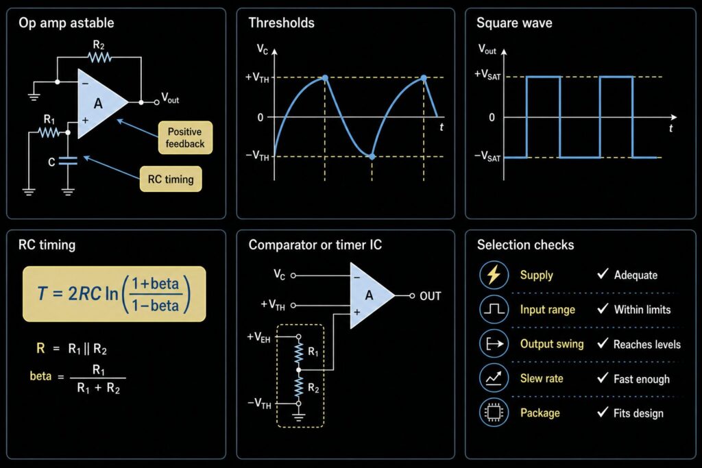
An op amp multivibrator is a timing circuit that can switch its output between a high level and a low level. In this article, the main focus is the astable op amp multivibrator, also called an op amp square wave generator. It has no stable output state. The output keeps changing because a capacitor charges and discharges through a resistor, while positive feedback sets the switching points.
Use this guide when you need a simple square wave, a low-frequency clock, a test signal, or a timing idea for a prototype. If your design needs exact duty cycle, logic-level output, high speed, low jitter, or guaranteed startup over temperature, compare the op amp circuit with a comparator IC, a timer IC, or a dedicated oscillator before you release the BOM. For broad sourcing, start with operational amplifier ICs, then confirm the exact ordering code.
What Is an Op Amp Astable Multivibrator?
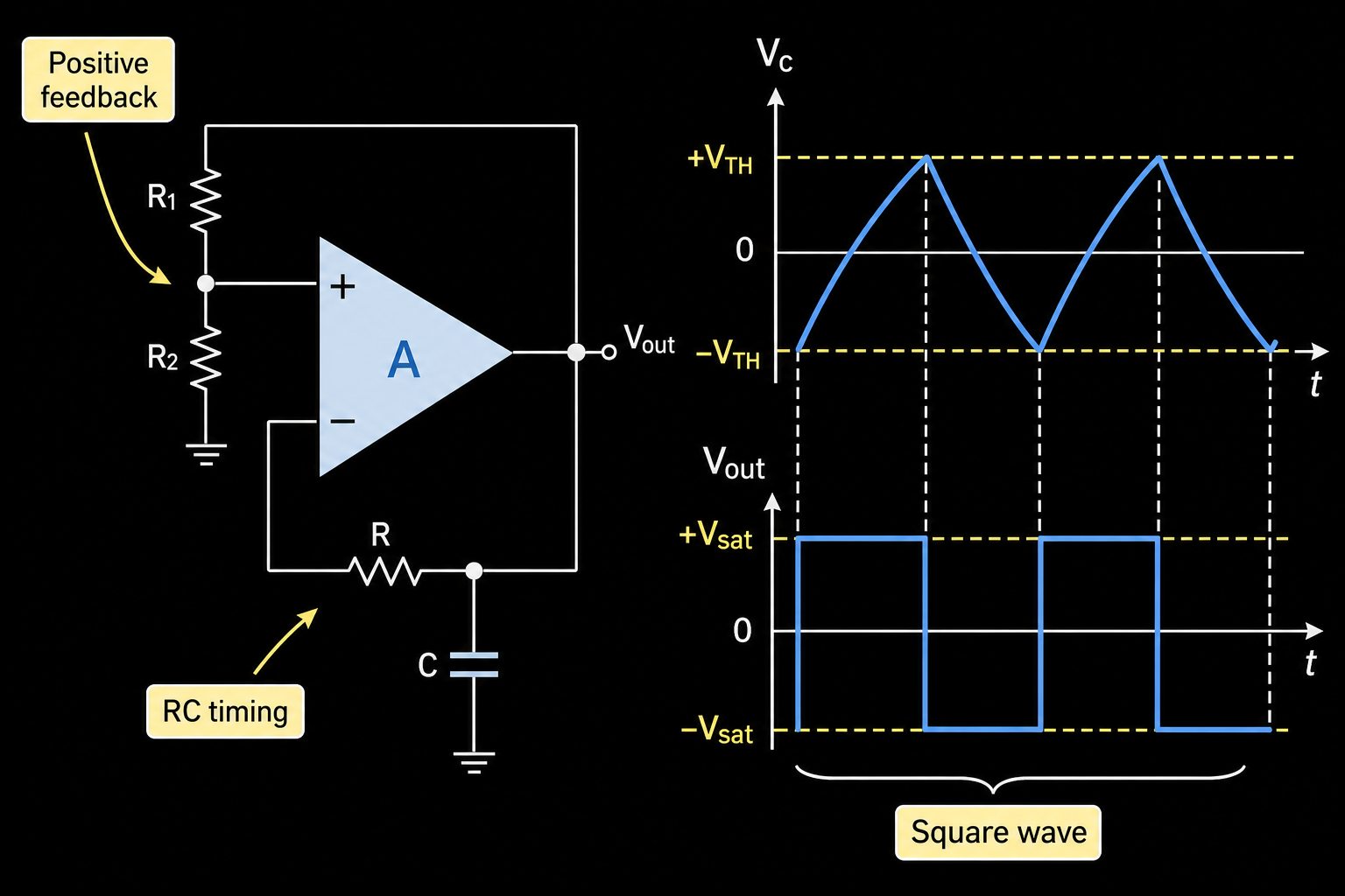
An op amp astable multivibrator is a relaxation oscillator. It uses the op amp as a switching device instead of as a linear amplifier. The output switches between a high state and a low state. A feedback network sends part of the output back to the non-inverting input, creating two switching thresholds. An RC network on the other input makes a rising and falling capacitor voltage.
The result is a square-wave output. Inside the circuit, the capacitor voltage is usually a ramp-like or curved charging waveform. The op amp changes state when the capacitor voltage crosses one of the feedback thresholds.
This topic is closely related to comparator circuits, but the function is different. For threshold-only switching and hysteresis, see the Op Amp Comparator guide. For one-shot pulse timing, see the Op Amp Monostable guide. An astable multivibrator instead uses positive feedback and RC timing to generate a continuous square wave.
How Positive Feedback Makes Two Switching Points
In a normal negative-feedback amplifier, the op amp tries to make the two input pins almost equal. In an astable multivibrator, the circuit uses positive feedback. Positive feedback makes the output move strongly toward one rail or the other rail.
A resistor divider feeds part of the output voltage back to the non-inverting input. If the output is high, the divider creates an upper threshold. If the output is low, the divider creates a lower threshold. The capacitor voltage is compared with those thresholds.
This is similar to a Schmitt trigger action. The important point is hysteresis: the switching point for going high is not the same as the switching point for going low. That difference keeps the output from chattering near one threshold.
For engineering work, record the resistor divider ratio, the real output high voltage, and the real output low voltage. Do not assume the op amp output reaches the exact supply rails unless the datasheet says it can under your load condition.
RC Timing and Frequency
The timing comes from one resistor and one capacitor, often called the RC network. When the output is high, the capacitor charges toward the high output level. When the capacitor reaches the upper threshold, the op amp switches low. Then the capacitor discharges or charges toward the low output level until it reaches the lower threshold. The cycle then repeats.
For a common symmetrical astable circuit with balanced charge and discharge paths and approximately symmetrical output levels, the period can be estimated as:
T = 2RC x ln((1 + beta) / (1 - beta))
Here, R is the timing resistor, C is the timing capacitor, and beta is the feedback divider fraction. If the divider gives beta = 0.5, the period is about:
T = 2.2RC
So the approximate frequency is:
f = 1 / (2.2RC)
This equation is a simplified estimate for this common circuit topology, not a universal multivibrator formula. Real frequency changes with resistor tolerance, capacitor tolerance, leakage, temperature, actual output-high and output-low voltages, input bias current, input common-mode range, switching recovery, and supply voltage.
Square Wave Output and Duty Cycle
A simple astable op amp multivibrator often gives a near 50% duty cycle when the charge and discharge paths are balanced and the switching thresholds are symmetrical. If the high and low output levels are not symmetrical, the duty cycle may shift.
If the circuit needs a controlled duty cycle, do not treat the basic two-resistor op amp circuit as enough. Check whether the design needs separate charge and discharge resistors, steering diodes, a comparator circuit, a timer IC, or a microcontroller timer output.
For sourcing, write the duty-cycle requirement in the RFQ or BOM notes. A request such as "op amp for 1 kHz square wave, 5 V single supply, near 50% duty cycle, CMOS input preferred" is much easier to verify than "op amp oscillator."
Single-Supply Designs Need Extra Checks
Many older op amp oscillator examples use dual supplies such as +/-15 V. Many current products use a single supply such as 3.3 V, 5 V, or 12 V. A single-supply circuit needs careful input and output checks.
First, make sure the input common-mode range includes the capacitor voltage at both switching points. If the capacitor voltage goes outside the allowed input range, the op amp may switch late, switch wrongly, or not switch at all.
Second, check output swing under load. A "rail-to-rail output" op amp may still have a voltage drop from each rail, especially when it drives current. The timing formula uses the real output high and low levels, not the ideal supply rails.
Third, check startup. Some oscillator circuits can power up in a state that starts slowly or needs a small imbalance to begin oscillation. In production, verify startup at minimum supply voltage, maximum temperature range, and worst-case RC values.
Op Amp Selection Checklist for Multivibrator Circuits
Use this checklist before adding an op amp multivibrator circuit to a production BOM.
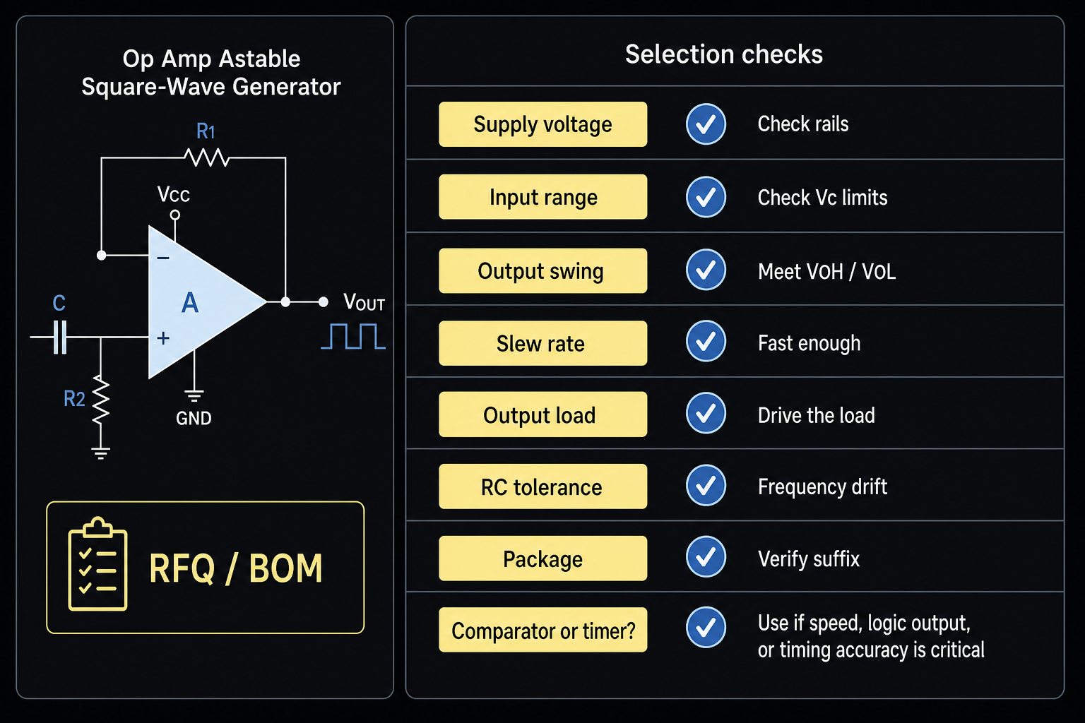
| Check | Why It Matters | RFQ / BOM Note |
|---|---|---|
| Supply voltage | The op amp must operate on the actual rails. | List 3.3 V, 5 V, 12 V, or dual supply. |
| Input common-mode range | The RC capacitor voltage must stay inside the valid input range. | Include threshold voltage range. |
| Output swing | The square wave high and low levels set timing and logic compatibility. | State required output high and low levels under load. |
| Slew rate | Slow edges can distort the square wave or limit frequency. | State target frequency and edge-speed need. |
| GBW and large-signal behavior | The op amp is switching, not only amplifying small signals. | Ask for suitability at the target frequency. |
| Output drive | The next stage may load the oscillator. | State load resistance, logic input, or buffer requirement. |
| Input bias current | Bias current can shift RC timing, especially with large timing resistors. | Give timing resistor value and capacitor type. |
| Temperature and tolerance | RC parts and op amp behavior change over temperature. | State expected timing tolerance. |
| Package and lifecycle | The correct package and active lifecycle reduce sourcing risk. | Verify package, suffix, lifecycle, and alternatives. |
This table is also useful for buyers. If an engineer sends only a circuit name, purchasing may not know which op amp family is acceptable. Add the supply, frequency, output load, timing tolerance, and package to the quote request.
When a Comparator or Timer IC Is Better
An op amp can be used in a multivibrator circuit, but an op amp is not always the best switching part. A comparator IC is built for threshold comparison. It often gives faster switching, cleaner logic output options, and better behavior when the input difference is large. Some op amps recover slowly after saturation, and that recovery can change timing.
A timer IC can also be better when the circuit needs a known timing block, adjustable duty cycle, strong output drive, or simple production support. A microcontroller timer may be better when firmware already controls the system timing.
Choose the op amp multivibrator when the frequency is modest, the load is light, the accuracy requirement is not tight, and the design already uses a suitable op amp. Choose a comparator, timer IC, or oscillator IC when speed, logic compatibility, timing accuracy, or startup confidence is more important.
How This Differs From an Integrator or Differentiator
An op amp integrator and an op amp differentiator are not the same as an astable multivibrator. An op amp integrator circuit uses a capacitor in the feedback path to create an output related to the time integral of the input. It is often used to make a ramp or shape a signal.
An op amp differentiator amplifier responds to the rate of change of the input signal. It is useful in edge and waveform analysis, but it also needs noise and bandwidth control.
The op amp multivibrator is different because it is a switching oscillator. It uses positive feedback plus RC timing to generate its own square wave rather than processing an external waveform with linear feedback.
Common Design Mistakes
One mistake is choosing the op amp only by supply voltage. Supply voltage is necessary, but it is not enough. The input common-mode range, output swing, slew rate, output load, and recovery behavior can decide whether the oscillator works.
Another mistake is using a very large timing resistor to save power without checking input bias current and capacitor leakage. A high resistor value makes small currents more important. The frequency may drift, or the circuit may fail at temperature extremes.
A third mistake is assuming the square wave can drive any digital input. Check the logic threshold of the next device. A 5 V op amp output may not be safe for a 3.3 V logic input. An op amp output may also need a buffer if it drives cables, LEDs, or low-resistance loads.
A fourth mistake is copying a tutorial circuit into a BOM without checking part status. Exact inventory, price, lead time, certifications, and authorized supply status are dynamic. Treat them as RFQ and BOM verification items.
Procurement Notes for BOM and RFQ Users
For one known part number, use Send Inquiry with the full ordering code, package, quantity, target date, and required manufacturer. For a project with several analog ICs, Upload BOM so the op amp, timing capacitor, resistor tolerance, and possible comparator or timer alternatives can be reviewed together.
Do not ask only for "an op amp for multivibrator." Add these details:
- Supply voltage and whether it is single-supply or dual-supply.
- Target frequency and allowed tolerance.
- Required output high and low levels.
- Load or next-stage input type.
- Timing resistor and capacitor values if already designed.
- Package preference, temperature grade, lifecycle need, and compliance documents to verify.
A sourcing team can then check suitable op amp families, possible comparator alternatives, package availability, and lifecycle risk without inventing stock or lead-time claims.
FAQ
What is an op amp multivibrator?
An op amp multivibrator is a switching timing circuit made with an operational amplifier. In an astable version, it uses positive feedback and an RC network to produce a repeating square wave.
How does an astable multivibrator using an op amp work?
The output switches high and low. A resistor divider creates two threshold voltages, and a capacitor charges and discharges through a resistor. When the capacitor crosses a threshold, the op amp changes output state.
Is an op amp multivibrator the same as a square wave generator?
It can work as a simple square wave generator. For accurate frequency, controlled duty cycle, fast edges, or logic-level output, compare it with a comparator, timer IC, microcontroller timer, or oscillator IC.
Can I use any op amp for an astable multivibrator?
No. Check supply voltage, input common-mode range, output swing, slew rate, output load, recovery behavior, package, and lifecycle. Some op amps are not suitable for switching near the rails or driving the next stage.
What is the formula for op amp astable multivibrator frequency?
For a common symmetrical circuit, T = 2RC x ln((1 + beta) / (1 - beta)), where beta is the feedback divider fraction. If beta = 0.5, a useful estimate is f = 1 / (2.2RC).
When should I choose a comparator instead of an op amp?
Choose a comparator when you need fast threshold switching, logic-compatible output, predictable overdrive behavior, or cleaner recovery from switching saturation. For more detail, see the Op Amp Comparator guide.
References and Further Reading
- Analog Devices University, Electronics Text Chapter 11: https://wiki.analog.com/university/courses/electronics/text/chapter-11
- Texas Instruments, "So Many Amplifiers to Choose From: Matching Amplifiers to Applications": https://www.ti.com/document-viewer/lit/html/SSZT983
- Texas Instruments, "Op Amps for Everyone" application report: https://www.ti.com/lit/an/sloa097/sloa097.pdf
Request Quote / Upload BOM
If this op amp multivibrator is part of a new design, send the target frequency, supply voltage, output load, package need, and timing tolerance with your RFQ. For a complete project list, use Upload BOM so the op amp, comparator option, timer option, timing capacitor, and resistor tolerance can be checked together. Dynamic items such as stock, price, lead time, certification, and authorized source status must be verified during the quote.