
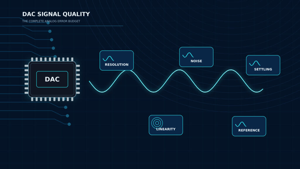
Yes, a DAC can improve signal quality when the problem is actually in the digital-to-analog conversion path: not enough resolution, poor linearity, high output noise, reference drift, slow settling, weak output drive, or a noisy built-in DAC block. But a better DAC IC will not automatically repair a bad analog design, weak power supply, noisy ground system, overloaded output, poor filtering, or unrealistic firmware timing.
For component buyers and engineers, the practical question is not "Does an expensive DAC sound better?" The better question is: "Which DAC specifications limit the output signal in this circuit?" If your design needs a controlled analog voltage or current, start with digital-to-analog converter ICs and define the output range, load, accuracy, update rate, reference, package, and sourcing constraints before you choose a part number.
Technical sources and current manufacturer lifecycle pages verified: September 1, 2026.
Quick Take: What Actually Controls DAC Signal Quality?
| Design Area | What It Affects | What to Check Before Sourcing |
|---|---|---|
| Resolution | Smallest ideal output step | Bits, output range, LSB size, noise floor |
| INL/DNL | Static accuracy and code-to-code behavior | Datasheet test conditions, monotonicity, endpoint method |
| Noise | Output stability and low-level signal purity | Output noise density, 0.1 Hz to 10 Hz noise, reference noise |
| Reference voltage | Full-scale accuracy and drift | Reference accuracy, temperature coefficient, load regulation, layout |
| Settling time | Accuracy after a code change | Final error band, output load, step size, update rate |
| Output buffer | Load drive, stability, bandwidth | Capacitive load, output current, external amplifier requirements |
| Grounding and filtering | Real PCB performance | AGND/DGND strategy, decoupling, routing, reconstruction or low-pass filter |
Will a DAC Improve Signal Quality?
A DAC can improve signal quality when it reduces a real conversion error. In an embedded control system, for example, replacing a low-resolution PWM-plus-filter output with a precision DAC IC may reduce ripple, improve output granularity, simplify calibration, and provide a cleaner setpoint. In a test instrument, a DAC with better linearity and faster settling may improve waveform accuracy or calibration repeatability. In a sensor excitation or bias circuit, a cleaner DAC output may reduce downstream measurement error.
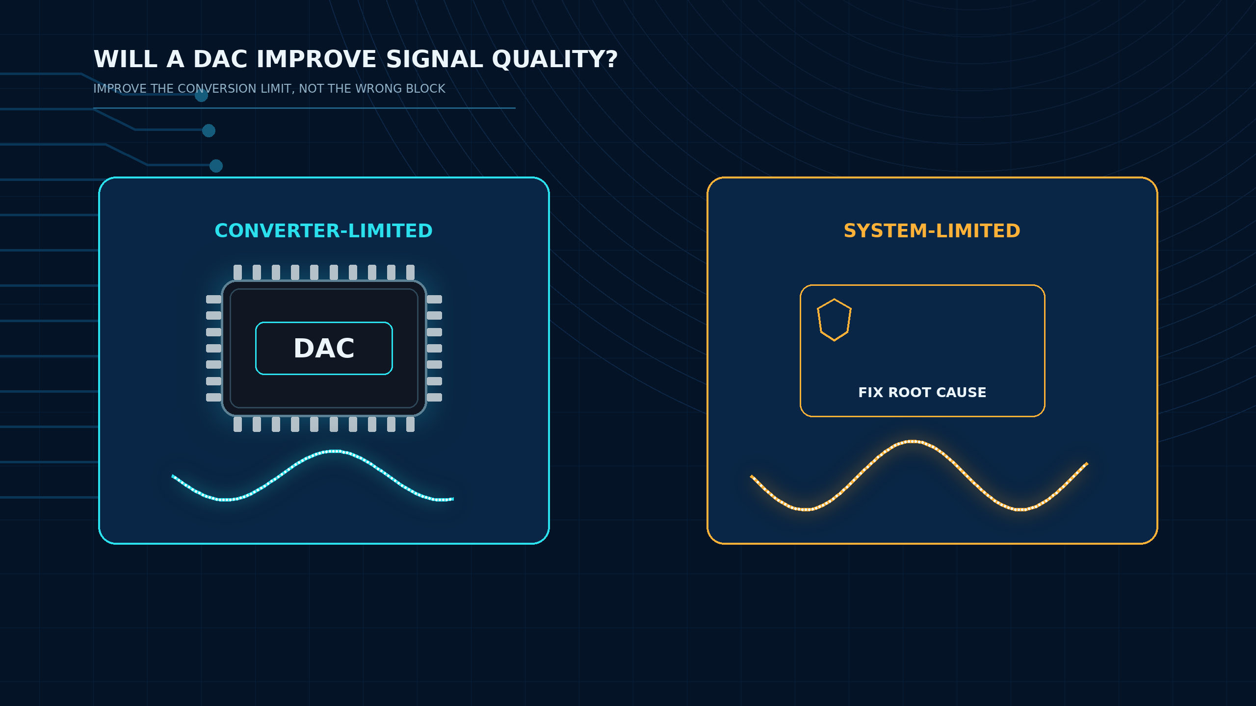
The improvement is not guaranteed by the word "DAC" alone. Every DAC output is limited by an error budget. Resolution defines the ideal step size, but it does not guarantee accuracy. INL and DNL describe static transfer errors. Noise adds uncertainty around the output level. The reference voltage often sets the full-scale output, so a poor reference can make a good DAC perform badly. Settling time tells you how quickly the output reaches a defined error band after a code change. Texas Instruments' Precision Data Converter Selection Guide groups these same parameters into a system-level selection process rather than treating bit count as a stand-alone quality score.
This is why two DAC ICs with the same number of bits can behave very differently in a real design. A 16-bit DAC with excessive noise, a drifting reference, or a stressed output amplifier may deliver less useful performance than expected. A lower-resolution DAC can be the better engineering choice if its speed, output range, stability, package, power, and lifecycle fit the application.
If you are still deciding whether the design needs a separate converter, read Do You Really Need a DAC IC? before locking the BOM. The answer depends on whether the analog output requirement can be met by PWM, a built-in DAC, a digitally controlled analog block, or an external DAC IC.
When a DAC Will Not Fix a Poor System Design
A better DAC IC will not fix every noisy or distorted output. If the system problem sits outside the DAC, the measured signal may not improve after the part is changed.
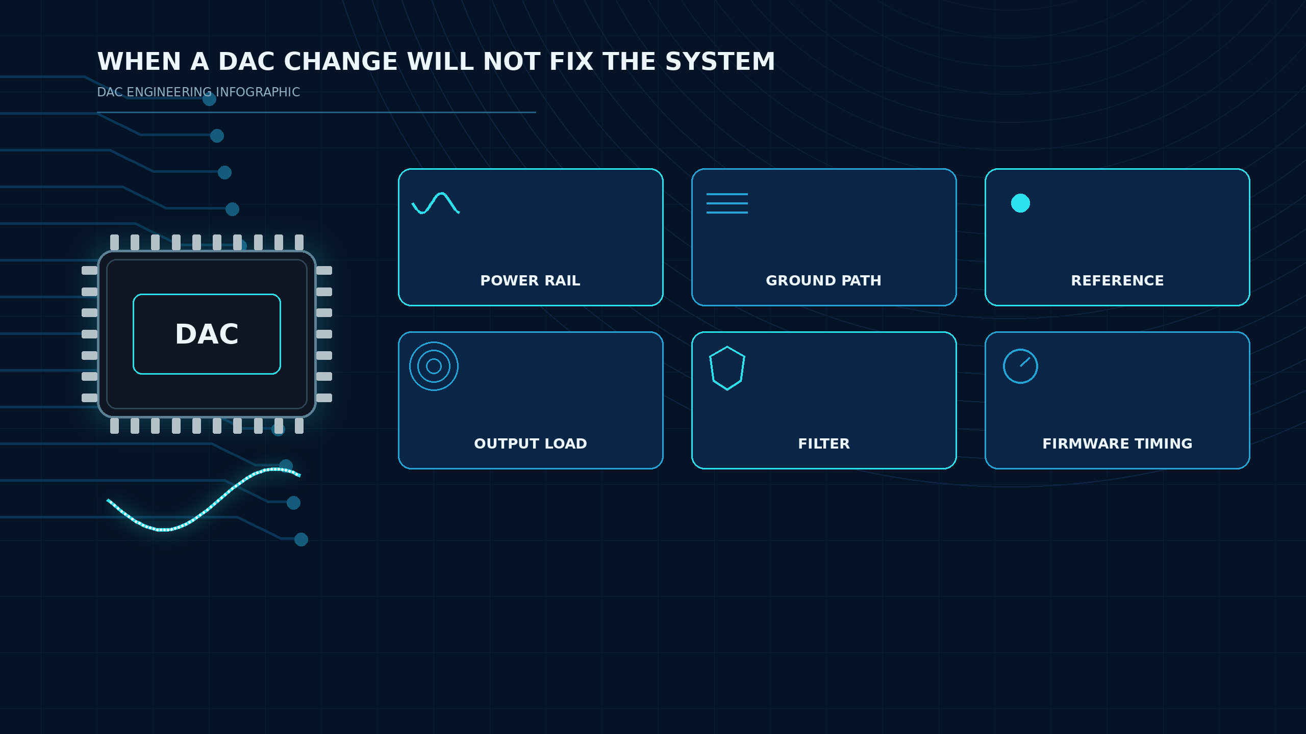
| System Problem | Why a DAC Change May Not Help | Better Engineering Action |
|---|---|---|
| Noisy power rail | DAC output and reference may inherit supply noise | Improve regulation, decoupling, PSRR strategy, and board placement |
| Poor grounding | Digital return currents can modulate analog output | Separate current paths, control return loops, follow data-converter layout guidance |
| Weak reference | DAC full-scale value moves with reference error | Choose and route a suitable reference; verify drift and load |
| Overloaded output | DAC buffer cannot drive the load cleanly | Add a stable output amplifier or reduce load demand |
| Missing filter | Images, glitches, or update noise remain at output | Add an application-specific low-pass or reconstruction filter |
| Firmware timing error | Output changes too fast for settling requirement | Match update rate to settling time and closed-loop bandwidth |
| Wrong converter choice | Built-in DAC or PWM cannot meet accuracy/noise needs | Compare built-in and external options in the BOM stage |
This matters for procurement because changing a part number after board bring-up can be expensive. Before replacing a DAC, confirm whether the failing measurement is dominated by converter specs, reference error, power integrity, output loading, analog layout, firmware timing, or downstream circuitry.
The same logic applies when comparing built-in DAC vs external DAC IC. An external DAC may improve accuracy, noise, channel count, or output range, but only when the support circuit is designed around those advantages.
Resolution, INL/DNL, Noise, Reference, and Settling Time
DAC Resolution
DAC resolution is the number of digital input bits used to divide the output range into code steps. For an ideal unipolar DAC, the approximate LSB size is:
For a 12-bit DAC over a 0 V to 4.096 V range, the ideal step size is about 1 mV. For a 16-bit DAC over the same range, the ideal step size is about 62.5 uV. This does not mean the 16-bit output is accurate to 62.5 uV in the actual circuit. Noise, reference error, gain error, offset error, INL, temperature drift, and layout can dominate the result.
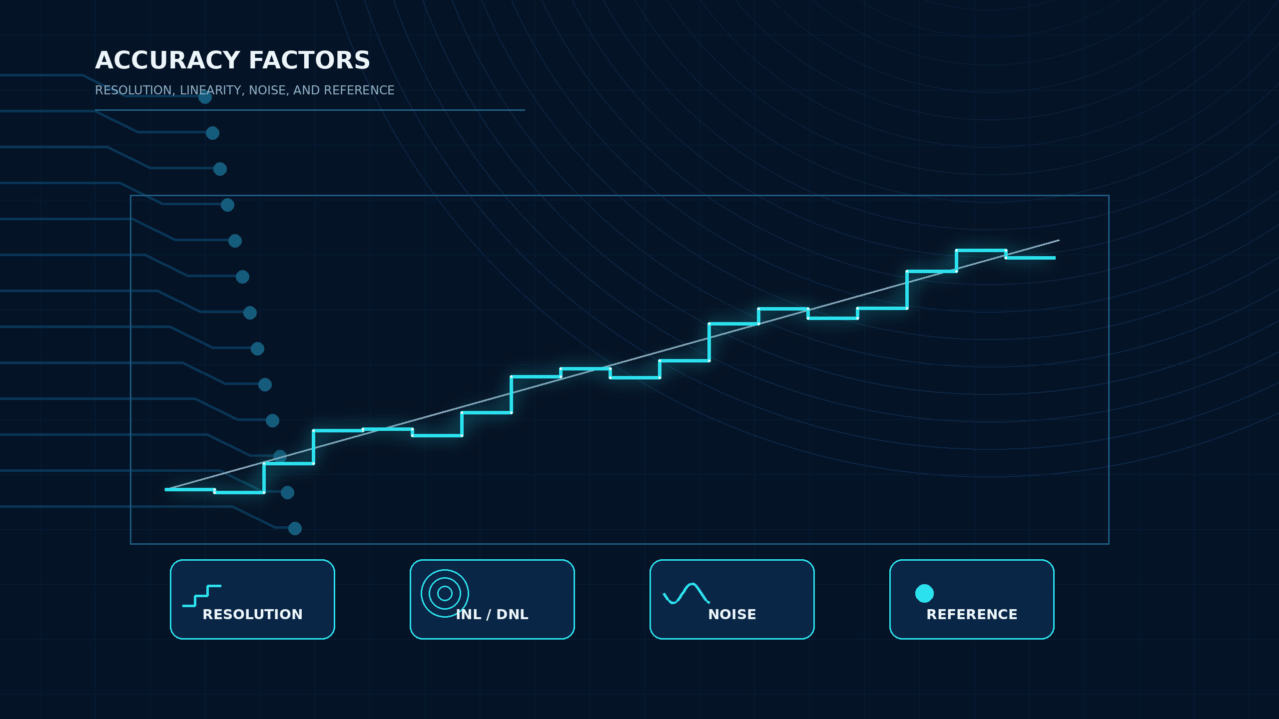
Resolution is useful only when the rest of the system can preserve it. If the output noise is several LSBs, or the load creates error larger than one step, extra bits may not improve the usable signal.
INL and DNL
Integral nonlinearity (INL) describes how far the DAC transfer curve deviates from an ideal line. Differential nonlinearity (DNL) describes the error in the size of each code step. For control loops, calibration outputs, programmable supplies, and waveform generation, INL and DNL help determine whether the output is predictable across the full code range.
DNL is also tied to monotonic behavior. A monotonic DAC output does not reverse direction when the input code increases. This can matter in closed-loop control, bias generation, and calibration systems where a code increase must not unexpectedly reduce the output. TI's precision DAC guide notes that DNL greater than 1 LSB can produce nonmonotonic behavior. Always read the selected datasheet definition and test method because endpoint, best-fit, and code-range assumptions may differ.
DAC Noise
Noise is one of the main reasons a high-resolution DAC may not deliver high usable accuracy. DAC noise can come from the internal architecture, output amplifier, reference input, digital coupling, power supply, and PCB layout. Datasheets may specify wideband noise, low-frequency noise, output noise density, or glitch-related behavior depending on the device type.
For slow precision outputs, low-frequency noise and reference drift can be more important than a headline bit count. For waveform outputs, broadband noise, glitch energy, output bandwidth, and settling behavior may matter more.
Reference Voltage
The reference voltage is central to DAC signal quality because it often defines the DAC transfer scale. A low-noise precision DAC connected to a noisy or drifting reference will not produce a stable precision output. Reference accuracy, temperature coefficient, long-term drift, output impedance, noise, load regulation, and PCB routing should be treated as part of the converter design, not as a separate afterthought.
Some DAC ICs include an internal reference. Others require an external reference. The best choice depends on accuracy, temperature range, board area, power budget, calibration plan, and supply-chain preference. Internal references can simplify design, while external references can provide tighter system-level control when properly routed and decoupled.
Settling Time
Settling time describes how long the DAC output takes to reach and remain within a specified error band after a code transition. The number is meaningful only with its test condition: step size, output load, final accuracy band, reference, and measurement method. A datasheet settling time to 1/2 LSB is not the same as settling to 0.1% or another accuracy window.
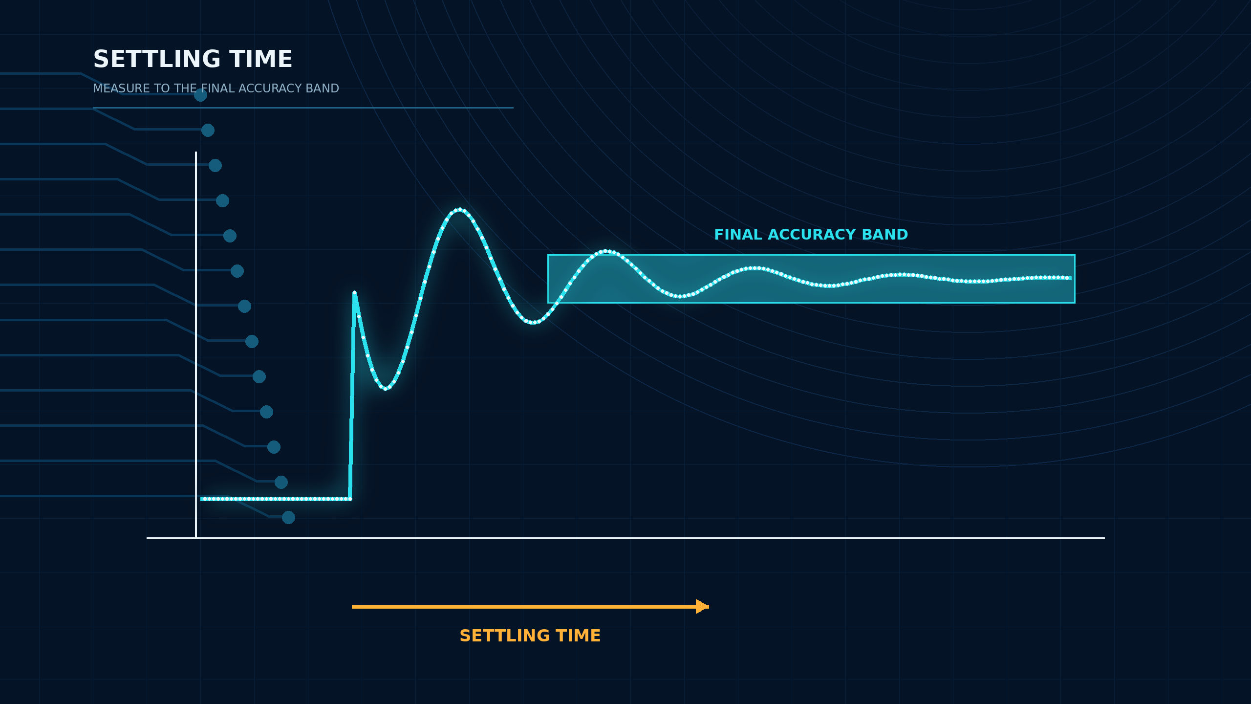
If firmware updates the DAC faster than the output can settle, the downstream circuit may see lag, distortion, control error, or waveform shape error. For waveform generation, programmable gain or offset control, fast calibration, and closed-loop systems, settling time should be reviewed with the load and filter in mind.
For a broader selection workflow, use How to Choose a Good DAC IC as the next design checklist.
Output Buffer, Reference Design, Grounding, and Filtering
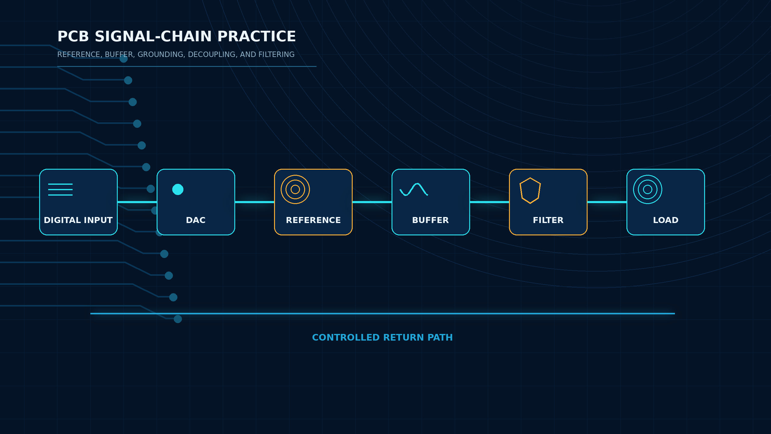
The DAC IC is only one part of the analog output chain. The output buffer, reference network, grounding approach, decoupling, and filtering often decide whether the theoretical datasheet performance appears on the PCB.
Output Buffer and Load Drive
Many voltage-output DACs include an internal output amplifier. That does not mean the DAC can drive any load. Check output current, short-circuit limits, capacitive-load stability, output swing near the rails, settling with load, and whether an external amplifier is recommended. If the DAC drives a cable, low-impedance load, sample-and-hold input, or filter network, the output stage must be checked as a complete circuit.
Current-output DACs need a different review. They often require an I/V conversion stage, load resistor, transformer, or amplifier depending on the application. The signal quality then depends on both the DAC and the chosen output network.
Reference Design
Treat the reference path like a precision analog input. Keep the reference source close where possible, follow the manufacturer's bypass guidance, avoid sharing noisy return current paths, and verify the reference can drive the DAC input behavior. A reference that looks accurate on a schematic can perform poorly if digital current spikes, poor decoupling, or long routing inject noise into the node.
Grounding and Decoupling
Data-converter layout is not solved by labeling one polygon "analog ground" and another "digital ground." The real goal is to control return currents so digital switching noise does not flow through sensitive analog reference, output, and measurement paths. Analog Devices' MT-031 grounding tutorial emphasizes current-path control, while MT-101 covers low-impedance decoupling practice. Use short decoupling loops, local bypass capacitors, clean reference routing, and the selected DAC manufacturer's layout guidance.
Filtering
Filtering depends on the output use case. A slow control voltage may need a low-pass filter to reduce update noise or glitch energy. A waveform output may need a reconstruction filter that balances bandwidth, phase shift, and image rejection. A calibration or bias output may need stability more than speed. Do not copy a filter from an audio converter article into an industrial DAC design without recalculating the load, bandwidth, and settling requirement.
DAC IC Signal Quality vs Consumer Audio DAC Claims
Search questions such as "Will a DAC improve sound quality?" and "Do DACs actually sound different?" often come from consumer audio discussions. For ApexComponent, those questions are useful only when they are translated into engineering signal quality.
A DAC IC can affect an audio or non-audio signal when it changes measurable performance: output noise, distortion, channel matching, linearity, clock-related behavior, filtering, output impedance, or analog stage design. But that does not turn this article into a USB DAC, headphone, speaker, DAP, or expensive audio accessory guide. A consumer product labeled as a digital to analog audio converter may include power supplies, clocks, firmware, output amplifiers, filters, connectors, enclosure design, and user-facing features beyond the DAC IC itself.
| Consumer Claim | Engineering Translation |
|---|---|
| "This DAC sounds better" | What changed in noise, distortion, output level, filtering, jitter sensitivity, or analog output design? |
| "More bits means better quality" | Is the system noise floor low enough to use the extra resolution? |
| "External DACs are always better" | Does the built-in DAC fail a measurable requirement? |
| "Expensive DAC means better signal" | Which datasheet specs and test conditions support the improvement? |
This approach keeps the article aligned with DAC IC sourcing rather than consumer audio recommendations.
DAC Signal Quality Checklist for BOM and RFQ
Before sending a DAC line item for sourcing, define the requirements that affect real performance:
| Requirement | What to Specify |
|---|---|
| Output type | Voltage output, current output, differential output, buffered or unbuffered |
| Output range | Unipolar, bipolar, rail-to-rail limits, reference-derived range |
| Resolution | Required bits and usable LSB size after noise and errors |
| Static accuracy | INL, DNL, offset error, gain error, monotonicity |
| Dynamic behavior | Settling time, glitch impulse, update rate, output bandwidth |
| Noise | Low-frequency noise, output noise density, reference noise contribution |
| Reference | Internal or external reference, voltage, drift, accuracy, decoupling |
| Interface | SPI, I2C, parallel, JESD-style interface, logic voltage |
| Channels | Single, dual, quad, multichannel synchronization needs |
| Package | Match the exact package drawing, land pattern, height, thermal limits, orderable suffix, and assembly constraints before release |
| Lifecycle | Check manufacturer lifecycle status, PCN/PDN notices, distributor status, and last-time-buy risk for the selected suffix |
| Sourcing data | Confirm stock, price, lead time, certification files, package availability, date code, and supplier channel in the current RFQ |
When the design has lifecycle risk or legacy part numbers, also review DAC IC lifespan, lifecycle, and replacement planning. A technically correct DAC is still a poor BOM choice if it is difficult to source, close to discontinuation, or not validated for the required package and compliance path.
FAQ
Will a DAC improve sound quality?
A DAC may improve sound quality only if the original audio signal path is limited by measurable DAC-related issues such as noise, distortion, output stage behavior, filtering, or reference and clock design. For engineering and BOM work, translate "sound quality" into measurable signal quality requirements instead of assuming any DAC upgrade is useful.
Do DACs actually sound different?
DAC-based products can measure and sometimes sound different because they include different DAC ICs, references, filters, clocks, output amplifiers, power supplies, and analog layouts. The DAC IC is only one part of that chain, so a sourcing decision should be based on datasheet specs, system requirements, and validation results rather than consumer audio claims.
Is higher DAC resolution always better?
No. Higher DAC resolution gives a smaller ideal LSB step, but usable performance also depends on INL, DNL, noise, reference quality, output buffer behavior, temperature drift, and PCB layout. Extra bits do not help much if the system noise floor is larger than the added resolution.
What DAC specs matter most for signal quality?
The most important specs are usually resolution, INL, DNL, output noise, reference accuracy and drift, settling time, output drive, glitch behavior, and interface timing. The priority depends on whether the DAC is used for slow control, precision calibration, waveform generation, biasing, audio, or test equipment.
When should I choose an external DAC IC instead of a built-in DAC?
Choose an external DAC IC when the built-in DAC cannot meet the required resolution, noise, accuracy, output range, settling time, channel count, load drive, temperature stability, or lifecycle requirements. If the built-in DAC already meets the measured error budget, an external DAC may add cost and sourcing complexity without improving the circuit.
External Sources
- Texas Instruments, Precision Data Converter Selection Guide
- Texas Instruments, Understanding Data Converters
- Texas Instruments, Precision Voltage References
- Analog Devices, MT-031: Grounding Data Converters
- Analog Devices, MT-101: Decoupling Techniques
Request a Quote for a Performance-Specified DAC IC
When the performance requirements are clear, use Request a Quote for the selected DAC IC or candidate list. Include target output range, resolution, INL/DNL needs, noise limit, reference choice, settling time, load condition, interface, channel count, package preference, operating temperature, quantity, delivery date, date-code requirement, and compliance documents.