
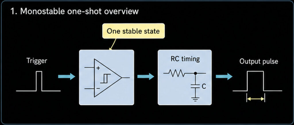
An op amp monostable is a one-shot pulse circuit. It normally stays in one stable state. When a trigger arrives, the output changes state for a set time, then returns by itself. The set time is mainly controlled by a resistor and capacitor, usually written as an RC timing network.
Use this guide if you need to understand an op amp monostable, size the pulse width, check trigger behavior, or decide whether a real comparator IC or a 555 timer is a better choice. If you already have a part number, package, supply voltage, pulse-width target, and quantity, use the operational amplifier ICs category or submit the BOM for sourcing review.
What Is an Op Amp Monostable?
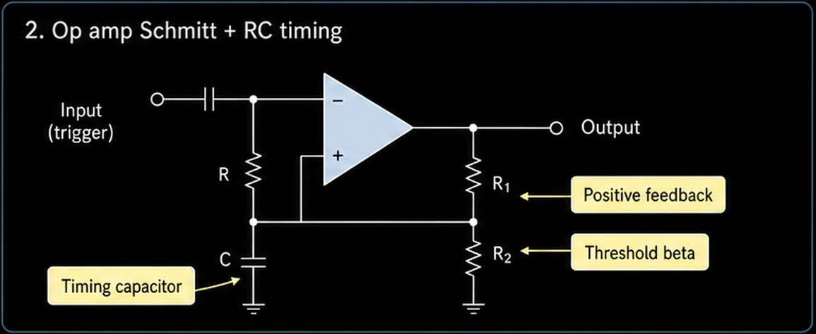
A monostable circuit has one stable state. It can be pushed into a temporary state by a trigger signal, but it will not stay there forever. After the timing period ends, the circuit returns to its normal state.
In an op amp monostable, the op amp is not used as a normal linear amplifier. It is used more like a threshold switch. Positive feedback gives the circuit two switching thresholds, similar to a Schmitt trigger. The timing capacitor then decides how long the output remains in the temporary state.
This makes the circuit useful for:
- Creating one output pulse from a short trigger.
- Stretching a narrow input event into a wider pulse.
- Shaping a trigger signal before another analog or logic stage.
- Adding a simple timing delay in an analog circuit.
The key buyer and design point is simple: the timing formula is only the start. A real BOM must also check op amp input range, output swing, slew rate, capacitor leakage, temperature drift, package, lifecycle, and whether a comparator or timer IC is the safer part family.
Monostable, Astable, Bistable: Do Not Mix Them
These words are close, but they do not mean the same circuit.
| Circuit type | Stable states | What it does | Owner page |
|---|---|---|---|
| Monostable | 1 | Makes one timed output pulse after a trigger | This page: /op-amp-monostable/ |
| Astable multivibrator | 0 | Keeps oscillating and makes a repeated square wave | /op-amp-multivibrator/ |
| Bistable circuit | 2 | Holds either state until another signal changes it | Separate latch / flip-flop topic |
| Comparator | Depends on input and hysteresis | Compares two voltages and switches output | /op-amp-comparator/ |
| 555 timer monostable | 1 timed state using timer IC internals | One-shot timing with trigger, threshold, reset, and discharge pins | Separate timer IC page |
This article stays on the op amp monostable owner topic: one-shot pulse, trigger, RC pulse width, reset, and retrigger behavior.
How the One-Shot Pulse Works
A simple op amp monostable has four important blocks:
| Block | What it does | What to verify in a real design |
|---|---|---|
| Op amp or comparator-like switch | Changes output state when the input crosses a threshold | Input common-mode range, output swing, recovery from saturation, supply voltage |
| Positive feedback network | Creates hysteresis and state memory | Resistor ratio, tolerance, threshold margin, noise immunity |
| RC timing network | Controls how long the temporary state lasts | Resistor value, capacitor value, leakage, tolerance, voltage rating, temperature coefficient |
| Trigger and reset path | Starts or clears the timing event | Trigger polarity, minimum pulse width, false-trigger filtering, reset priority |
Here is the usual sequence:
- The circuit sits in its stable output state.
- A trigger pulse moves the switching threshold enough to change the output state.
- The output change starts the timing capacitor charging or discharging through a resistor.
- When the capacitor voltage reaches the switching threshold, the op amp output returns to the stable state.
- The capacitor must recover before the next trigger can be handled correctly.
That last point is often missed. A one-shot is not only "trigger, pulse, done." The circuit also needs recovery time before the next trigger.
RC Pulse Width: The Useful Design Rule
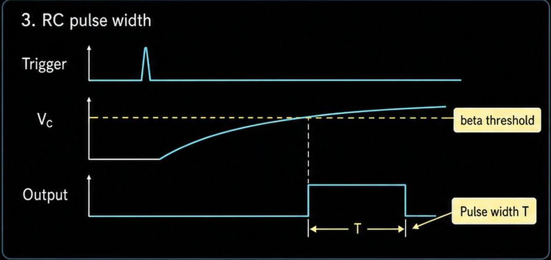
The pulse width is set mainly by the RC timing network and the feedback threshold.
A simple design rule is:
T = -R * C * ln(1 - beta)Where:
Tis the output pulse width in seconds.Ris the timing resistor in ohms.Cis the timing capacitor in farads.betais the feedback fraction that sets the switching threshold.
If the feedback divider is close to 50%, beta is about 0.5, and the formula becomes:
T is about 0.69 * R * CThis is an approximation, not a purchase specification. In a real op amp monostable, the exact pulse width can shift because of diode clamp voltage, output swing, input offset, capacitor leakage, resistor tolerance, capacitor tolerance, temperature, and supply voltage.
Example Pulse-Width Check
| Target | Example value | Design meaning |
|---|---|---|
| Timing resistor | 100kOhm | Higher values reduce current but increase leakage sensitivity |
| Timing capacitor | 100nF | Must have suitable voltage rating and low enough leakage |
| Approximate pulse width | 0.69 x 100kOhm x 100nF = 6.9ms | Good for a millisecond pulse, but tolerance must be checked |
| If resistor is +/-1% and capacitor is +/-10% | Pulse can move noticeably | Use tighter parts or calibrate if timing matters |
For long pulses, capacitor leakage becomes more important. For short pulses, op amp slew rate, propagation delay, trigger edge speed, and PCB layout become more important.
Trigger Behavior
The trigger is the event that starts the one-shot pulse. In many op amp monostable circuits, the trigger is a fast negative-going or positive-going edge that pushes the threshold across the switching point.
A good trigger path should:
- Have the correct polarity for the circuit.
- Be large enough to cross the threshold with margin.
- Be narrow enough not to hold the circuit in the wrong state.
- Reject slow drift and noise that could cause false triggering.
- Avoid violating the op amp input voltage limits.
An RC differentiator may be used to turn a square wave edge into a short trigger spike. That can be helpful when the monostable should respond only to the edge, not to the full input pulse. The differentiator time constant should be much shorter than the input pulse width, so the trigger spike starts the one-shot and then disappears.
For production designs, do not choose the trigger components only from a textbook diagram. Check input voltage range, source impedance, clamp diode current, ESD protection limits, and the next stage's logic threshold.
Reset and Retrigger Behavior
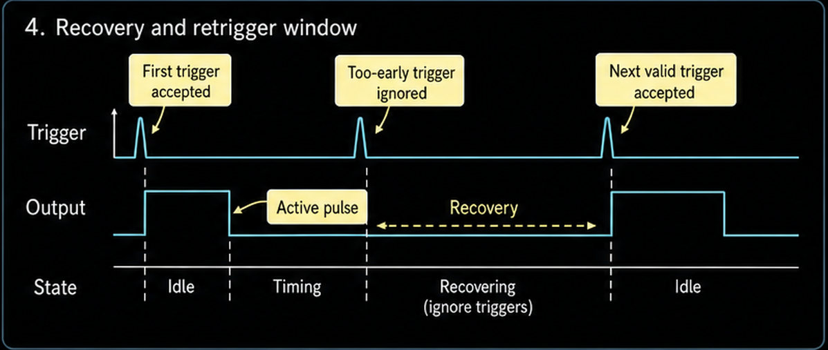
Reset and retrigger behavior decide what happens when another event arrives too soon.
| Behavior | Meaning | Design concern |
|---|---|---|
| Non-retriggerable | A second trigger during the active pulse is ignored or has no useful effect | Good when each event needs one fixed pulse |
| Retriggerable | A second trigger extends or restarts the pulse | Useful for missing-pulse detectors or activity timers |
| Resettable | A reset signal forces the output back to the stable state | Useful when a controller must cancel timing |
| Recovery-limited | The timing capacitor must return near its starting voltage before the next trigger | Important at high trigger rates |
A basic op amp monostable is usually recovery-limited. During the output pulse, and often during capacitor recharge, a second trigger may not start a clean new timing period. If your system needs retriggerable behavior, design that feature directly instead of assuming the basic circuit will do it.
For digital systems, a 555 timer or logic monostable may be easier because it has defined trigger, threshold, discharge, and reset pins. For analog systems, an op amp or comparator-based one-shot can be useful when the trigger threshold, supply rails, and analog signal path must be customized.
Op Amp Monostable vs Comparator vs Timer IC
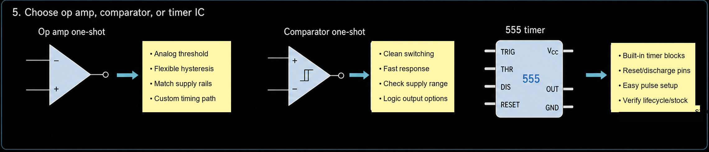
An op amp monostable often uses comparator-like behavior, but that does not mean every op amp is a good comparator. A real comparator IC is designed for switching, propagation delay, output logic interface, and operation near threshold. Some comparators also include or support hysteresis to prevent noisy multiple transitions.
| Choice | Use it when | Be careful about |
|---|---|---|
| Op amp monostable | The design is analog-heavy and the one-shot threshold must match an analog signal path | Output saturation recovery, input common-mode range, output swing, slew rate |
| Comparator-based monostable | You need cleaner threshold switching and faster logic-level output | Open-drain pull-up, propagation delay, hysteresis resistor tolerance |
| 555 timer monostable | You need a standard timing IC with trigger, threshold, reset, discharge, and stronger output drive | Timer supply range, output current, timing capacitor leakage, package and lifecycle |
| Logic monostable | The system is mainly digital and needs defined logic thresholds | Logic family voltage, reset/retrigger truth table, timing tolerance |
For sourcing, this distinction matters. If the BOM says "op amp," do not replace it with a comparator or 555 timer without engineering approval. If the BOM says "timer IC," do not replace it with a random op amp circuit just because both can make a pulse.
Op Amp Selection Checks For a One-Shot Circuit
Use this checklist before sending an RFQ or approving a substitute.
| Check | Why it matters |
|---|---|
| Supply voltage | The op amp must operate on the available rails, such as single-supply or dual-supply operation |
| Input common-mode range | Trigger and threshold voltages must stay inside the allowed input range |
| Output swing | The output must reach levels that make the timing network and next stage work |
| Output current | The op amp must drive the load or next stage without overload |
| Slew rate and recovery | Slow output movement can distort short pulses |
| Input offset voltage | Offset shifts the actual switching threshold |
| Bias current | Bias current can disturb high-value timing resistors |
| Timing capacitor type | Leakage and temperature drift change pulse width |
| Resistor tolerance | Threshold and timing values depend on resistor accuracy |
| Package and temperature grade | Must match the board layout and operating environment |
| Lifecycle and availability | Verify during RFQ; do not assume stock or long-term supply |
For older examples that mention a 741 op amp, treat it as a learning example, not a default design choice. Modern single-supply, rail-to-rail, low-power, or high-speed circuits usually need a different op amp or a real comparator.
Procurement Notes for BOM and RFQ Teams
When asking for sourcing support, include more than the words "op amp monostable."
Send these fields if available:
- Required pulse width and tolerance.
- Trigger polarity, trigger voltage, and trigger pulse width.
- Supply voltage and whether the design is single-supply or dual-supply.
- Output load and required output logic level.
- Timing resistor and capacitor values, tolerances, and voltage ratings.
- Preferred op amp, comparator, or timer IC part number.
- Package, temperature grade, and quantity.
- Any lifecycle, RoHS/REACH, AEC-Q, or customer approval requirements that must be verified.
A sourcing team can then check the part number, package, lifecycle, stock, price, lead time, and compliance status. Those items are dynamic and should be verified during RFQ or BOM review, not written as fixed facts in a tutorial.
Common Mistakes
Mistake 1: Treating the Op Amp Like a Linear Amplifier
In this circuit, the op amp is switching between output states. It is not staying in its normal linear gain region. That means output saturation, recovery time, and input overdrive can matter.
Mistake 2: Ignoring Capacitor Leakage
For long pulse widths, a large timing resistor and capacitor may look good on paper. In real life, capacitor leakage and input bias current can change the timing. Use the datasheet and test the final board.
Mistake 3: Assuming It Is Retriggerable
Many basic one-shot circuits are not cleanly retriggerable. A second trigger may be ignored or may produce a bad pulse if the capacitor has not recovered.
Mistake 4: Replacing a Timer IC With an Op Amp
A 555 timer includes internal trigger, threshold, latch, discharge, reset, and output-driver blocks. An op amp circuit can copy some behavior, but it is not a pin-compatible or functional replacement without design validation.
Mistake 5: Copying a Diagram Without Checking the Rails
Many tutorial circuits use dual supplies or ideal output swings. A real board may use 3.3V, 5V, or another single supply. The op amp must support the input and output levels on that supply.
FAQ
What is an op amp monostable used for?
It is used to make one timed output pulse after a trigger event. Common uses include pulse shaping, simple delay timing, edge detection, and analog trigger conditioning.
Is an op amp monostable the same as a 555 timer?
No. Both can make a one-shot pulse, but a 555 timer is a dedicated timer IC with trigger, threshold, reset, discharge, and output-driver functions. An op amp monostable is a custom analog circuit built around switching thresholds and an RC timing path.
How do I calculate the pulse width of an op amp monostable?
Start with the RC timing network and threshold ratio. A common estimate is T = -R*C*ln(1 - beta), and if beta is about 0.5, T is about 0.69*R*C. Then check real tolerance, leakage, output swing, and temperature effects.
Can I retrigger an op amp monostable?
Only if the circuit is designed for that behavior. A basic op amp monostable often needs the timing capacitor to recover before it can accept the next trigger cleanly.
Should I use an op amp or a comparator for a monostable circuit?
Use a comparator when threshold switching, propagation delay, logic output, and noise behavior are important. Use an op amp only when its datasheet supports the required input range, output swing, speed, and recovery behavior.
Internal Links
- Browse operational amplifier ICs when the BOM already names an op amp family or part number.
- Read the op amp comparator guide when threshold switching and hysteresis are the main topic.
- Read the op amp multivibrator guide when the circuit should oscillate continuously instead of making one pulse.
- Use the operational amplifier building blocks hub to compare this circuit with other op amp functions.
External Sources
- Electronics Tutorials: Op-amp Monostable
- Texas Instruments: Comparator With and Without Hysteresis Circuit, SBOA219B
- Texas Instruments: xx555 Precision Timers, SLFS022K
- Analog Devices: MT-083: Comparators
Request Quote or Upload BOM
If you have one or two known part numbers, use Send Inquiry and include package, quantity, supply voltage, timing target, and temperature grade.
If the project has many analog ICs, timing capacitors, resistors, diodes, comparators, or timer IC options, use Upload BOM. The BOM review should verify part number, package, lifecycle, stock, price, lead time, compliance, and whether the selected part family is an op amp, comparator, timer IC, or logic monostable.

Alice lee
Business Manager
Focused on the electronic components sector, the author shares industry knowledge, product insights, and sourcing perspectives related to modern electronics manufacturing. With close attention to market trends, component applications, and supply chain developments, the content is designed to support engineers, buyers, and businesses in making more informed decisions.