
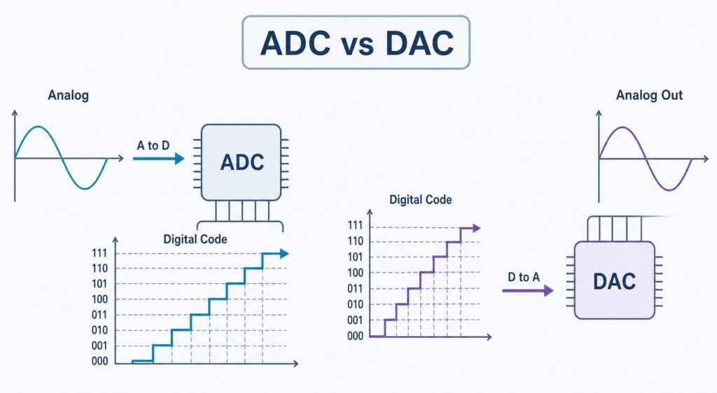
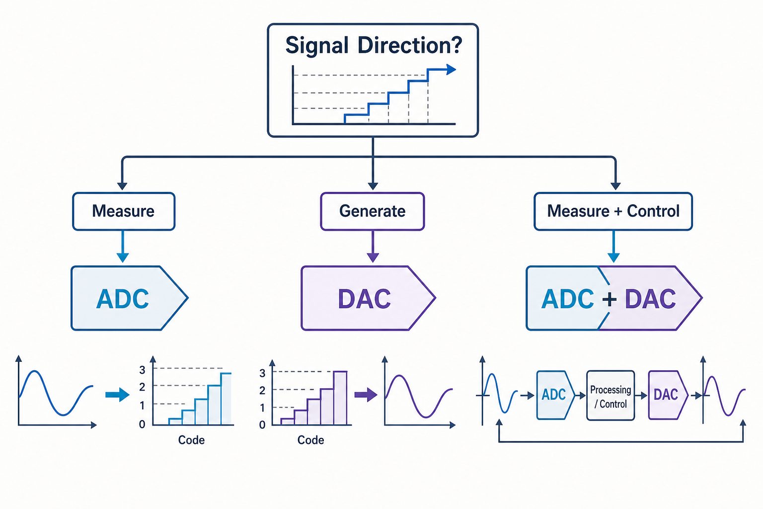
The main difference between an ADC and a DAC is the direction of conversion. An analog-to-digital converter (ADC) converts an analog input into digital data. A digital-to-analog converter (DAC) converts digital data into an analog voltage or current.
Use an ADC when a processor must measure a real-world signal such as a sensor voltage, current-sense output, microphone signal, battery level, temperature signal, or pressure signal. Use a DAC when digital electronics must generate or control an analog level such as a voltage setpoint, current command, waveform, bias voltage, or audio output.
| Question | Practical Answer |
|---|---|
| What does an ADC do? | Converts an analog input into a digital code. |
| What does a DAC do? | Converts a digital code into an analog voltage or current. |
| Which direction is ADC? | Analog → digital. |
| Which direction is DAC? | Digital → analog. |
| Can one replace the other? | No. They perform opposite functions. |
| Can one system use both? | Yes. Measurement-and-control systems often use an ADC and a DAC together. |
ADC vs DAC in One Sentence
An ADC measures an analog signal for digital processing; a DAC creates an analog output from digital data.
Microcontrollers, processors, DSPs, and FPGAs process digital values, while sensors, power stages, speakers, actuators, and many control nodes operate with analog signals. ADCs and DACs are data converters that connect these two domains.
| Converter | Full Name | Input | Output | Main Role |
|---|---|---|---|---|
| ADC | Analog-to-Digital Converter | Analog voltage, or a conditioned analog signal | Digital code or sample stream | Measurement |
| DAC | Digital-to-Analog Converter | Digital code | Analog voltage or current | Output generation / control |
How Does an ADC Work?
An ADC converts a continuous analog signal into a numerical representation that digital electronics can process. At a conceptual level, the process includes sampling, quantization, and digital encoding. The exact internal implementation depends on the ADC architecture.
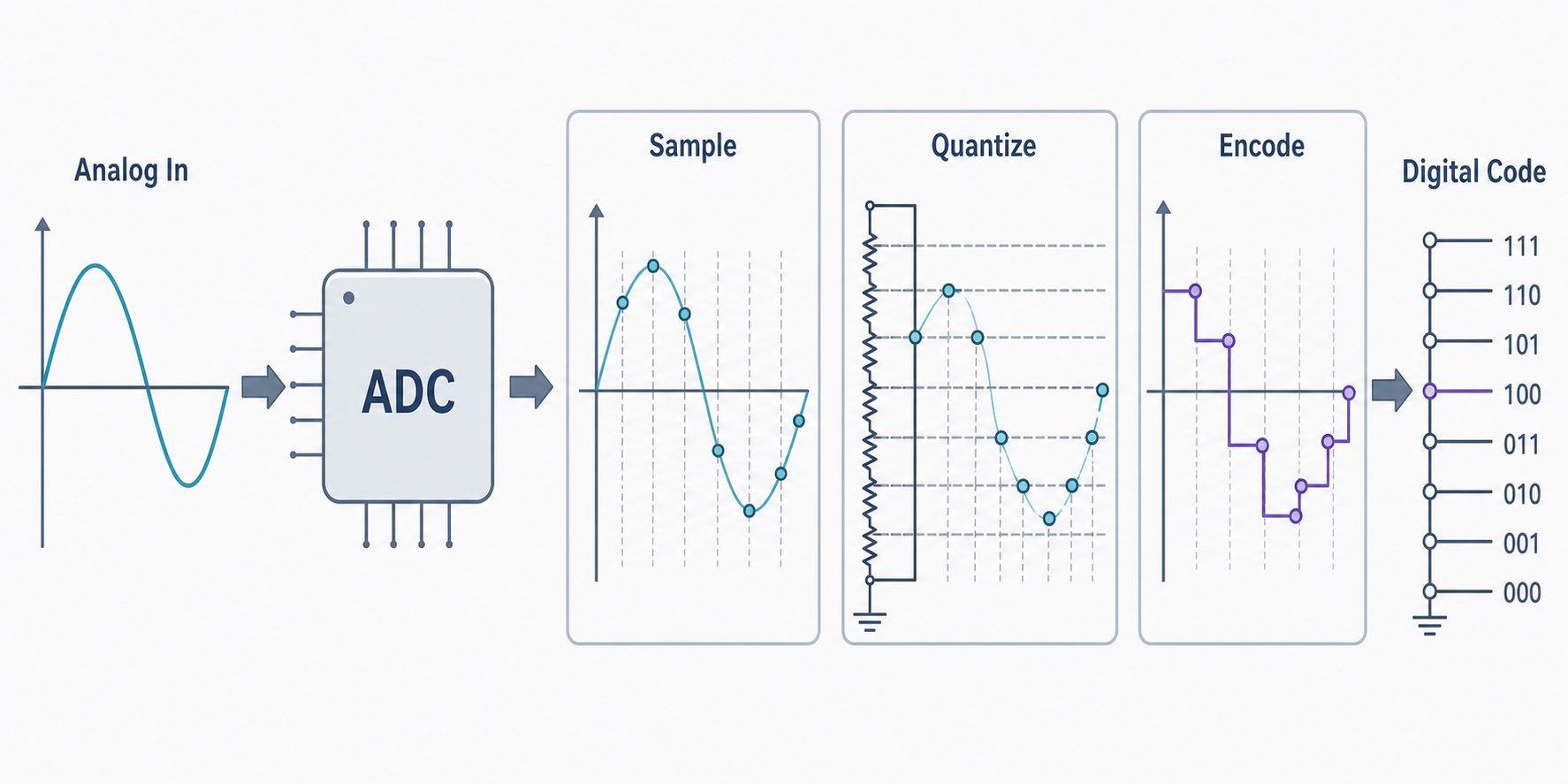
Important ADC specifications include resolution, sampling rate or throughput, input range, reference requirements, noise, INL, DNL, ENOB, latency, channel count, interface, power consumption, and package. The analog front end also matters: source impedance, amplifier settling, anti-alias filtering, and reference quality can limit the performance of the complete signal chain.
For a fuller explanation of the conversion process, see How Does an Analog-to-Digital Converter Work?
How Does a DAC Work?
A DAC accepts a digital input code and produces a corresponding analog output. Depending on the device, the output may be a buffered voltage, an unbuffered voltage, or a current that requires additional circuitry.
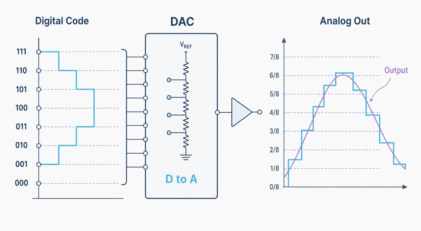
Key DAC specifications include resolution, output range, reference configuration, settling time, update rate, INL, DNL, monotonicity, glitch impulse, noise, output drive, channel count, interface, power, and package. A DAC used for waveform generation may also need a reconstruction filter after the converter.
For more DAC fundamentals, see Digital to Analog Converter: DAC Basics.
The Core Difference: Signal Direction
The easiest way to distinguish the two devices is to follow the signal direction:
Analog signal → ADC → Digital code
Digital code  → DAC → Analog signal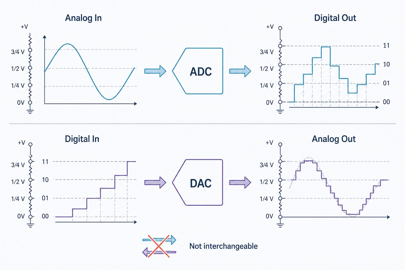
| Design Question | ADC Side | DAC Side |
|---|---|---|
| What enters the converter? | An analog signal to be measured | A digital code from an MCU, DSP, FPGA, processor, or interface |
| What leaves the converter? | Digital data | Analog voltage or current |
| Main system task | Measure | Generate / control |
| Important timing terms | Sampling rate, throughput, latency | Settling time, update rate |
Basic Transfer Relationships
For an ideal N-bit converter with a full-scale span from Vmin to Vmax, a useful first-order estimate of one code step is:
Ideal LSB size ≈ (Vmax - Vmin) / 2^NFor a common unipolar straight-binary DAC, a simplified ideal relationship is:
Vout ≈ Vmin + (Code / 2^N) × (Vmax - Vmin)ADC and DAC in the Same Signal Chain
Many mixed-signal systems use both types of converter. The ADC measures what is happening, the processor makes a decision, and the DAC creates a controlled analog response.
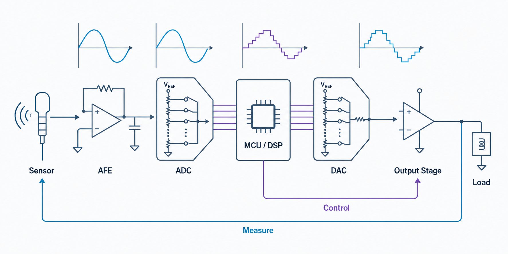
Sensor → Analog Front End → ADC → MCU / DSP → DAC → Output Stage → LoadThis structure is common in industrial control, data acquisition, programmable power supplies, automated test equipment, instrumentation, calibration systems, and some motor-control support circuits.
ADC vs DAC Comparison Table
| Attribute | ADC | DAC |
|---|---|---|
| Conversion direction | Analog → digital | Digital → analog |
| Main purpose | Measure an analog signal | Generate an analog signal |
| Typical input | Sensor output, AFE output, current-sense voltage, battery monitor node | Digital code from MCU, DSP, FPGA, processor, or digital interface |
| Typical output | Binary code or digital sample stream | Analog voltage or current |
| Key timing parameters | Sampling rate, throughput, latency, aperture uncertainty | Settling time, update rate |
| Important static errors | Offset, gain error, INL, DNL | Offset / zero-scale, gain error, INL, DNL |
| Important dynamic concerns | SNR, SINAD, ENOB, distortion, aliasing, clock jitter | Settling, glitch impulse, noise, distortion, output filtering |
| Can replace the other? | No | No |
Why Do We Need ADCs and DACs?
Digital systems cannot directly process every real-world analog quantity, and digital logic cannot directly create every required analog output. ADCs and DACs provide the conversion boundary.
- Use an ADC when the system must measure an analog signal.
- Use a DAC when the system must generate a controlled analog output.
- Use both when the system must measure, process, and then control an analog quantity.
How to Choose Between ADC, DAC, or Both
| Need | Choose | First Specifications to Check |
|---|---|---|
| Measure a sensor voltage with an MCU | ADC | Resolution, input range, sampling rate, reference, interface, source-drive requirements |
| Read a current-sense amplifier output | ADC | Input range, noise, sampling rate, channel count, reference, common-mode limits of the front end |
| Generate a programmable voltage setpoint | DAC | Resolution, output range, settling time, output drive, reference, accuracy |
| Create an analog waveform from digital samples | DAC | Update rate, settling time, distortion, glitch energy, interface, reconstruction filter |
| Build a feedback measurement-and-control loop | ADC + DAC | ADC latency/noise plus DAC settling/output range and total loop bandwidth |
ADC Selection Checklist
- Resolution and required effective resolution (ENOB)
- Sampling rate / throughput and signal bandwidth
- Input range, input type, and source impedance
- Reference voltage, reference noise, and drift
- INL, DNL, offset, gain error, SNR, and distortion
- Architecture: SAR, delta-sigma, flash, integrating, or another type
- Latency, channel count, interface, package, power, and operating temperature
DAC Selection Checklist
- Resolution and required DC accuracy
- Voltage-output or current-output architecture
- Output range, reference configuration, and gain
- Settling time and update rate
- INL, DNL, monotonicity, noise, and glitch impulse
- Output drive capability and external amplifier/filter requirements
- Channel count, interface, package, power, and operating temperature
For both converter types, sourcing teams should also verify the exact manufacturer part number, package, temperature grade, lifecycle status, compliance requirements, lead time, and approved alternatives. A pin-compatible device is not automatically a functional replacement; the electrical and timing specifications still require datasheet verification.
Common Mistakes
Mistake 1: Asking Whether a DAC Converts Analog to Digital
It does not. Analog-to-digital conversion is the ADC function. A DAC starts with digital data and produces an analog output.
Mistake 2: Treating ADC and DAC Devices as Alternatives
They perform opposite jobs. Matching resolution, package, or interface does not make an ADC and a DAC interchangeable.
Mistake 3: Comparing Only Bit Count
Resolution is only one specification. ADC performance also depends on input range, noise, sampling rate, reference quality, linearity, and the analog front end. DAC performance also depends on output range, settling time, noise, linearity, output drive, and glitch behavior.
Mistake 4: Confusing Sampling Rate with DAC Update Rate
An ADC sampling rate tells you how often the input is converted. A DAC update rate tells you how often a new output code can be applied. For a DAC, the output must also settle to the required accuracy after a code change.
Mistake 5: Ignoring the Analog Circuit Around the Converter
The converter does not work in isolation. ADCs may need input buffers, anti-alias filters, and a low-noise reference. DACs may need output buffers, current-to-voltage conversion, or reconstruction filters. PCB grounding, decoupling, reference routing, and signal integrity can directly affect measured performance.
Related ADC and DAC Guides
FAQ
What is the difference between an ADC and a DAC?
An ADC converts an analog input into digital data. A DAC performs the reverse operation and converts digital data into an analog voltage or current.
How do ADCs and DACs work?
An ADC measures an analog input and maps it to one of a finite number of digital codes. A DAC receives a digital code and maps it to a corresponding analog output level. The internal circuitry depends on the converter architecture.
Can a DAC convert analog to digital?
No. Analog-to-digital conversion requires an ADC.
Can an ADC generate an analog output?
No. An ADC produces digital output data. If a system needs a programmable analog output, it normally requires a DAC or another analog output circuit.
Can a circuit use both an ADC and a DAC?
Yes. Closed-loop control, instrumentation, programmable power supplies, calibration systems, and test equipment commonly use an ADC for measurement and a DAC for controlled analog output.
Is a higher-bit ADC or DAC always better?
No. More bits provide finer ideal code spacing, but real performance also depends on noise, linearity, reference quality, bandwidth, speed, layout, and the surrounding analog circuitry.
Which converter should I choose for a sensor?
If the sensor produces an analog voltage or a conditioned analog signal that must be measured digitally, use an ADC. The correct ADC depends on the sensor bandwidth, signal range, noise level, accuracy target, sampling rate, and interface.
Need Help Sourcing ADC or DAC ICs?
Send the manufacturer part number, package, quantity, target delivery date, and any approved alternative requirements. For multi-line projects, you can also submit your BOM for part-number and availability review.
References and Further Reading
- Texas Instruments — Understanding Data Converters (SLAA013)
- Texas Instruments — AN-156: Specifying A/D and D/A Converters
- Analog Devices — ADC Architectures
- Analog Devices University — Analog to Digital Conversion
Always verify the latest datasheet for the exact orderable part number before making a design or replacement decision.