
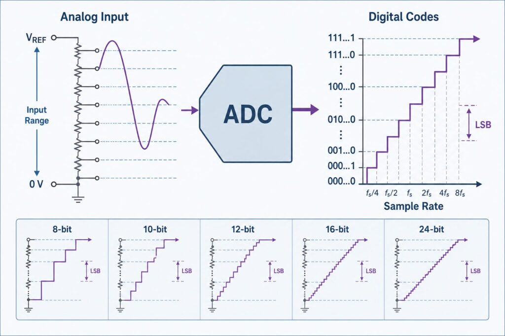
Choosing an analog-to-digital converter is not simply a matter of selecting the highest bit count. A 24-bit ADC provides 16,777,216 digital codes, but the real measurement quality also depends on input range, noise, effective resolution, reference performance, analog front-end design, sampling or output data rate, digital filtering, and PCB layout.
For low-level sensors, bridge measurements, precision instruments, weigh scales, temperature systems, and narrow-band data acquisition, a 24-bit converter can be a strong choice. For faster control loops or wider-band signals, a lower-bit SAR ADC—or a newer high-resolution SAR architecture—may provide lower latency and easier signal-chain design.
- 24-bit resolution does not mean 24 noise-free bits. Check noise tables, ENOB, effective resolution, and noise-free resolution.
- LSB size depends on full-scale input span. A smaller input span produces a smaller ideal code width, but only if noise and linearity are good enough to use it.
- Sampling rate is not the same as usable signal bandwidth. This is especially important for delta-sigma ADCs with digital filters.
- Reference noise, PGA settings, input common-mode range, settling, and PCB leakage can dominate a precision design.
Quick ADC Resolution Comparison
| Nominal Resolution | Ideal Codes | Typical Use | Main Design Caution |
|---|---|---|---|
| 8-bit | 256 | Coarse controls, simple monitoring | Large code width |
| 10-bit | 1,024 | Basic MCU sensing | May be too coarse for small sensor changes |
| 12-bit | 4,096 | General data acquisition, power monitoring, sensors | Reference, driver, and layout errors become more important |
| 16-bit | 65,536 | Precision sensing and industrial measurement | Noise and analog-front-end performance often limit usable resolution |
| 24-bit | 16,777,216 | Low-level precision measurement and high-resolution DAQ | Nominal bits can be much higher than effective or noise-free resolution |
What Does ADC Resolution Mean?
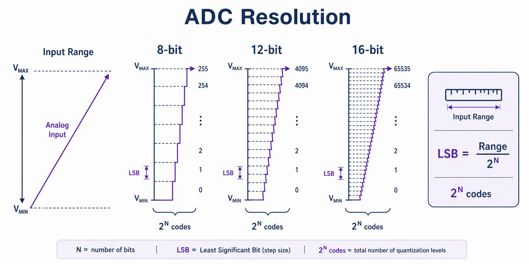
An N-bit ADC provides 2N possible digital codes. For quick selection work, the ideal code width can be written as:
Ideal LSB ≈ Full-Scale Input Span / 2^NFor a converter with an input span from VMIN to VMAX:
FSR = VMAX - VMIN

Ideal LSB ≈ FSR / 2^N2^N - 1 step intervals between endpoint codes. For design calculations, use the transfer-function definition in the specific ADC datasheet.
For an ideal 24-bit ADC with a 3.3 V input span:
LSB ≈ 3.3 V / 16,777,216
    ≈ 0.1967 µV
That number is only the ideal digital step size. It does not mean the converter can reliably distinguish every 0.1967 µV change in a real circuit.
LSB, Reference Voltage, and Input Range
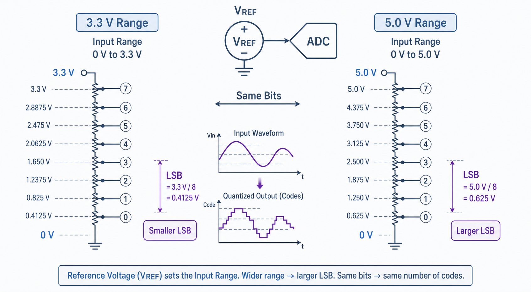
The reference voltage often determines or strongly influences the ADC full-scale input range. Many precision ADCs also include a programmable gain amplifier (PGA), which can map a small sensor signal across more of the converter range.
| Full-Scale Input Span | 8-bit LSB | 10-bit LSB | 12-bit LSB | 16-bit LSB | 24-bit LSB |
|---|---|---|---|---|---|
| 3.3 V | 12.89 mV | 3.22 mV | 0.806 mV | 50.35 µV | 0.1967 µV |
| 5.0 V | 19.53 mV | 4.88 mV | 1.221 mV | 76.29 µV | 0.2980 µV |
A smaller range gives a smaller ideal LSB, but this only helps if the reference, input amplifier, ADC noise, offset, gain error, and PCB layout are good enough to support that smaller signal level.
24-bit Does Not Mean 24 Effective Bits
This is the most important point when selecting a 24-bit ADC. Nominal resolution describes the output word width. It does not directly tell you how many stable or accurate bits the system delivers.
ENOB
Effective number of bits (ENOB) is commonly used for dynamic AC performance. It is derived from SINAD when the ADC is tested with a sine-wave input:
ENOB = (SINAD - 1.76 dB) / 6.02 dBThis relationship is useful for dynamic measurements, but it is not the same as DC effective resolution or noise-free resolution.
Effective Resolution
For precision DC or low-frequency measurements, datasheets may specify RMS input-referred noise. A useful estimate is:
Effective Resolution ≈ log2(FSR / RMS Input Noise)Noise-Free Resolution
Noise-free resolution is based on peak-to-peak noise and is closer to the number of output bits that can remain stable without code flicker:
Noise-Free Resolution ≈ log2(FSR / Peak-to-Peak Input Noise)These three terms—ENOB, effective resolution, and noise-free resolution—should not be treated as interchangeable. For precision 24-bit ADCs, always read the noise table at the exact data rate, gain setting, input range, and filter mode you intend to use.
How Many ADC Bits Do You Actually Need?
Start with the smallest input change that must be detected. In an ideal noiseless system:
Required Codes = Full-Scale Input Span / Smallest Required Change

Required Bits = ceil(log2(Required Codes))
Example: a sensor produces 0 to 3.3 V, and the system must resolve 2 mV changes.
Required Codes = 3.3 V / 0.002 V
               = 1650

log2(1650) ≈ 10.69

Ideal minimum = 11 bits
An 11-bit ideal converter meets the mathematical requirement, but a real design needs margin for sensor noise, reference error, offset, gain error, nonlinearity, temperature drift, and calibration uncertainty. A 12-bit or higher device may therefore be more practical.
For a 24-bit system, the same principle applies: do not select 24 bits merely because the sensor signal is small. First calculate the required measurement resolution, then verify the converter's actual noise performance.
Sampling Rate Basics
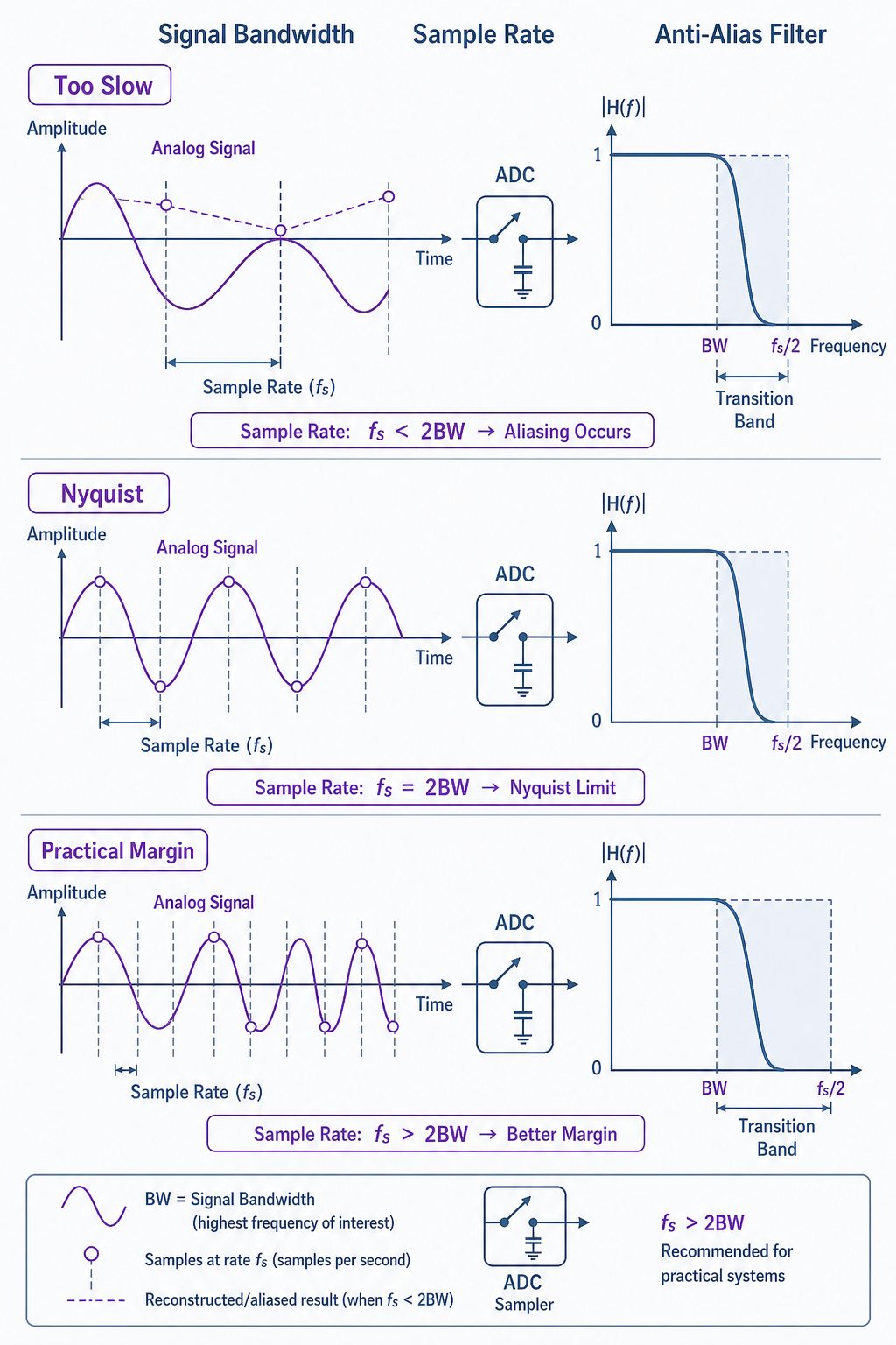
Sampling rate is the number of conversions or samples produced per second. For a conventional sampled system, the sample rate must be greater than twice the highest frequency component that must be represented:
fs > 2 × fMAXThis is the Nyquist lower bound, not a complete ADC selection rule. Real systems also need:
- anti-alias filter transition band,
- input acquisition and settling time,
- multiplexer settling time,
- digital-filter latency,
- control-loop timing margin,
- enough samples for the required algorithm or waveform analysis.
Sample Rate, Output Data Rate, Bandwidth, and Latency
These terms become especially important with 24-bit delta-sigma ADCs.
| Term | What It Means | Why It Matters |
|---|---|---|
| Modulator sample rate | Internal high-rate sampling inside a delta-sigma converter | Usually much higher than the final output rate |
| Output data rate (ODR) | Rate at which filtered conversion results are delivered | Does not automatically equal usable analog bandwidth |
| Signal bandwidth | Frequency range passed with acceptable amplitude and phase response | Depends on the selected digital filter and ADC architecture |
| Settling time / latency | Time required before a new result is valid after a step, channel switch, gain change, or reset | Critical for multiplexed sensors and control systems |
A delta-sigma ADC may output data at thousands of samples per second while its useful passband is substantially lower because of the digital filter. Conversely, SAR ADCs usually have a more direct relationship between conversion rate and usable signal bandwidth, but their analog input must settle accurately during the acquisition period.
Which ADC Architecture Fits a 24-bit Design?
Delta-Sigma ADC
Many precision 24-bit measurement ADCs use delta-sigma architecture. They combine oversampling, noise shaping, and digital filtering to provide excellent low-frequency noise performance. Some also integrate PGAs, reference buffers, excitation current sources, and 50/60 Hz rejection.
They are well suited to bridge sensors, weigh scales, temperature measurement, pressure sensing, and other narrow-band precision applications. See our Delta-Sigma ADC guide for the architecture details.
SAR ADC
SAR converters are often selected when lower latency and higher throughput are important. Modern precision SAR ADCs can reach very high nominal resolution, including 24-bit devices, but they usually require careful input-driver, reference, acquisition, and layout design.
For the conversion process and input-settling requirements, see SAR ADC Explained.
Dual-Slope / Integrating ADC
Integrating converters are very useful in digital multimeters and slow precision measurement because the integration window can strongly reject periodic interference such as 50 Hz or 60 Hz mains noise. Their main trade-off is conversion speed. See Dual-Slope ADC Explained.
8-bit vs 10-bit vs 12-bit vs 16-bit vs 24-bit ADCs
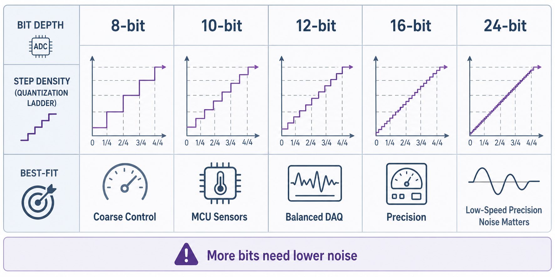
| Resolution | When It Makes Sense | What to Verify |
|---|---|---|
| 8 to 10 bit | Simple controls and coarse embedded sensing | Input range, MCU reference, sample rate |
| 12 bit | General sensors, power monitoring, DAQ | Reference, input driver, INL/DNL, acquisition time |
| 16 bit | Precision industrial sensing | Noise, offset, drift, reference, layout, calibration |
| 24 bit | Low-level or high-dynamic-range precision measurement | Noise table, ODR, filter bandwidth, PGA, reference, common-mode range, settling, PCB leakage |
Practical 24-bit ADC Selection Checklist
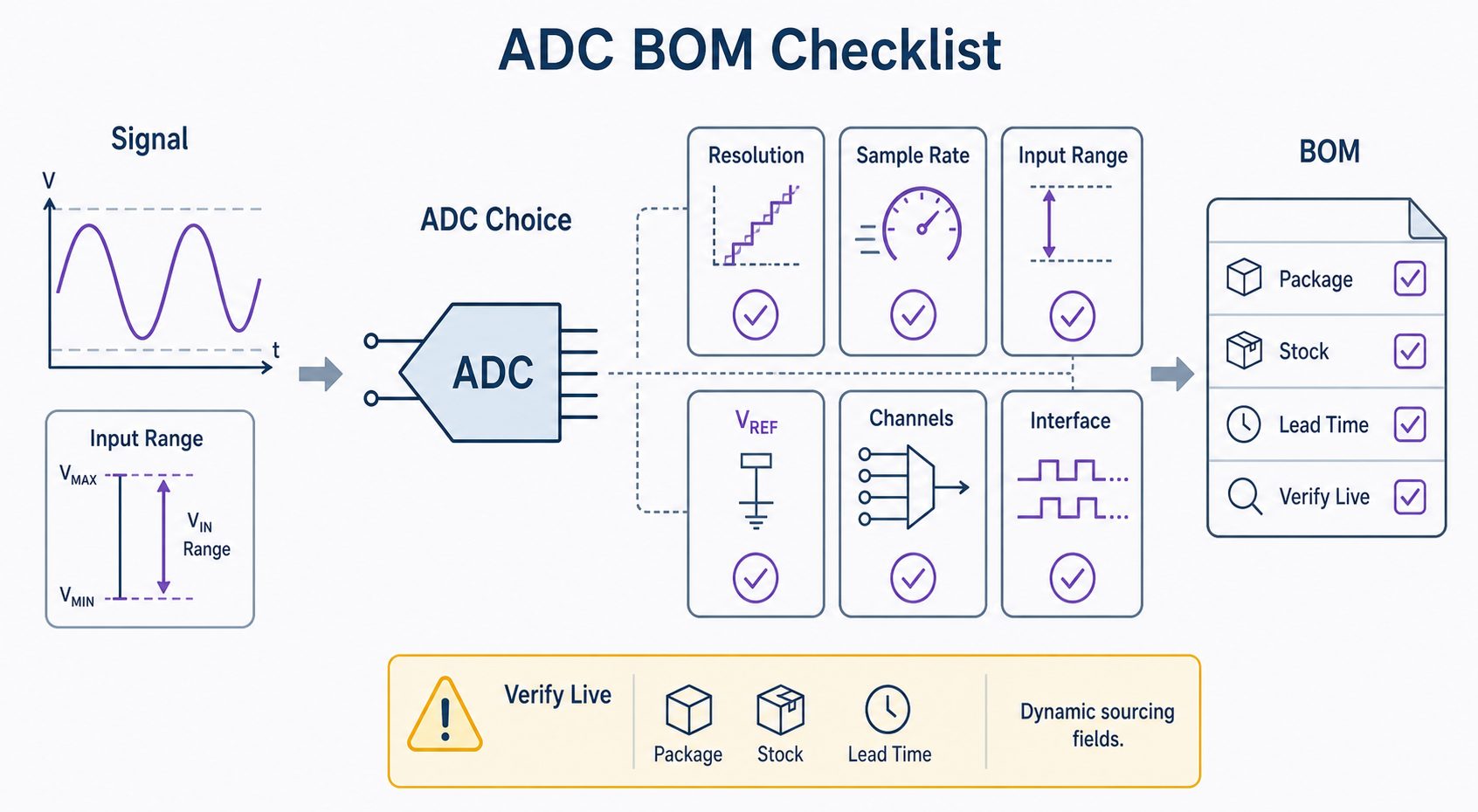
| Parameter | What to Check |
|---|---|
| Nominal resolution | Output word length: 12, 16, 18, 20, 24 bits, etc. |
| Effective / noise-free resolution | Use the datasheet noise table at the required gain and output data rate. |
| Input range | Unipolar or bipolar, single-ended or differential, full-scale span, overrange capability. |
| Input common-mode range | Especially important for differential ADCs and integrated PGAs. |
| PGA | Gain range, noise at each gain, input range, overload recovery, and settling after gain changes. |
| Reference | Internal or external reference, allowable voltage, noise, drift, reference input current, and buffer requirements. |
| Sampling / output data rate | Required per-channel throughput, not just aggregate converter rate. |
| Filter bandwidth | Passband, notch frequencies, stopband, group delay, latency, and settling behavior. |
| 50/60 Hz rejection | Check exact data-rate and filter settings that provide line-frequency rejection. |
| DC accuracy | Offset error, gain error, INL, drift, and calibration options. |
| Dynamic performance | SNR, SINAD, ENOB, THD, SFDR when measuring AC signals. |
| Input drive | Source impedance, RC filter, settling, kickback, input buffer, and amplifier stability. |
| Channels / multiplexer | Channel count, crosstalk, per-channel rate, and settling after switching. |
| Interface | SPI, I²C, parallel, LVDS, JESD204, or MCU-integrated interface as required. |
| Power and supplies | Analog/digital supply voltages, power modes, reference supply, and power-up timing. |
| Temperature / package | Operating temperature, package size, thermal behavior, assembly requirements. |
| Lifecycle | Confirm manufacturer lifecycle status, revision, package availability, and long-term supply requirements before BOM lock. |
Worked Example: Selecting a 24-bit ADC for a Bridge Sensor
Assume a bridge sensor and analog front end produce a differential signal of ±20 mV. The required usable measurement resolution is 5 µV, and the signal bandwidth is below 20 Hz.
The full differential span is 40 mV:
Required Codes = 40 mV / 5 µV
               = 8,000

Required Ideal Bits = ceil(log2(8,000))
                    = 13 bits
Mathematically, 13 bits is enough to create 8,000 ideal code intervals. But the application may still benefit from a 24-bit delta-sigma ADC because its integrated PGA and digital filtering can reduce the external gain requirement and improve low-frequency measurement performance.
The correct selection question is therefore not “Do I need 24 bits?” but:
- What is the ADC RMS and peak-to-peak noise at the required PGA gain?
- What noise-free resolution is available at the selected output data rate?
- Does the input common-mode range include the bridge output?
- Does the digital filter provide the required 50/60 Hz rejection?
- What is the settling time after channel or gain changes?
- Will reference noise, excitation noise, PCB leakage, and amplifier offset dominate the ADC?
Reference Voltage and Noise Matter More at 24 Bits
At high resolution, reference performance is part of the measurement path. Reference noise and drift can directly modulate the conversion result. If the sensor is excited from the same reference used by the ADC, a ratiometric architecture can cancel some reference-related gain error, but only when the circuit and ADC input range support that approach.
Check:
- reference noise over the actual signal bandwidth,
- temperature coefficient,
- long-term drift when relevant,
- reference input impedance or dynamic current demand,
- required bypass capacitors and reference buffer stability.
PCB Layout for 24-bit ADCs
A 24-bit converter can resolve extremely small ideal voltage steps, so board-level leakage and noise that are insignificant in a 10-bit system may become dominant.
- Keep high-impedance sensor inputs clean and short.
- Follow the manufacturer grounding and decoupling recommendations.
- Place reference bypass components close to the ADC reference pins.
- Separate fast digital edges from sensitive analog inputs and references.
- Control leakage from flux residue, humidity, connectors, protection devices, and PCB surface contamination.
- Review thermocouple effects at dissimilar metal junctions for microvolt-level DC measurements.
- Verify that the input amplifier remains stable with any RC network driving the ADC.
Common ADC Selection Mistakes
- Choosing 24 bits before defining the required noise floor.
- Using ideal LSB size as the expected real-world accuracy.
- Confusing ENOB with noise-free resolution.
- Assuming output data rate equals signal bandwidth.
- Ignoring digital-filter latency and settling.
- Ignoring input common-mode range when using a PGA.
- Using a noisy or poorly driven reference.
- Ignoring per-channel rate and settling in multiplexed systems.
- Assuming Nyquist alone defines a safe sampling rate.
- Ignoring offset, gain drift, INL, calibration, PCB leakage, and temperature effects.
Related ADC Guides
- How Does an Analog-to-Digital Converter Work? ADC Basics Explained
- ADC vs DAC: Difference Between DAC and ADC Converters
- SAR ADC Explained
- Delta-Sigma ADC Explained
- Dual-Slope ADC Explained
- Flash ADC Explained
FAQ
What is the ideal LSB size of a 24-bit ADC?
For quick calculations, divide the full-scale input span by 224. A 3.3 V span gives about 0.1967 µV per ideal code. The actual stable measurement resolution will be worse if noise, drift, or nonlinearity are larger than this value.
Does a 24-bit ADC provide 24-bit accuracy?
No. Nominal resolution is the digital output word length. Real accuracy depends on noise, INL, offset, gain error, reference accuracy, temperature drift, calibration, and the analog front end.
What is the difference between ENOB and noise-free resolution?
ENOB is generally a dynamic metric derived from SINAD with a sine-wave input. Noise-free resolution is a low-frequency or DC-oriented metric based on peak-to-peak input-referred noise. They describe different aspects of ADC performance.
Is a delta-sigma ADC always the best choice for 24-bit measurement?
No. Delta-sigma ADCs are common for narrow-band precision measurement because of their noise shaping and digital filtering. A precision SAR ADC can be better when low latency, fast settling, or wider bandwidth is more important.
What sampling rate should I choose?
Start from the required signal bandwidth, then check anti-alias filtering, architecture, per-channel throughput, digital-filter bandwidth, latency, and settling time. For delta-sigma ADCs, do not use output data rate as a direct substitute for usable signal bandwidth.
Need Help Matching an ADC to Your BOM?
Send the required part number or your electrical requirements, including resolution, input range, sample or output data rate, channel count, interface, package, and temperature range. Alternative candidates should be verified against the original datasheet before design approval.
Send InquiryReferences and Further Reading
- Texas Instruments — Understanding Data Converters (SLAA013)
- Analog Devices — MT-004: ADC Input Noise, Effective Resolution, and Noise-Free Resolution
- Analog Devices — How to Calculate ENOB for ADC Dynamic Performance Measurement
Always use the latest manufacturer datasheet and errata for final component selection. Input ranges, noise performance, filter behavior, package options, and lifecycle status are device-specific.