
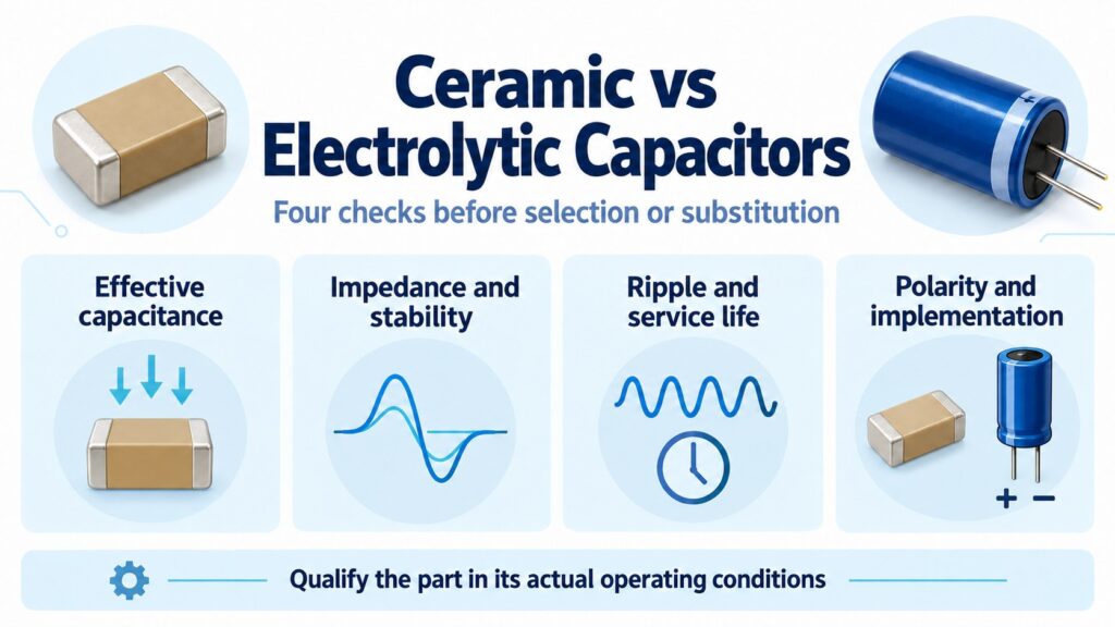
Ceramic and electrolytic capacitors often perform different jobs on the same board. A multilayer ceramic capacitor (MLCC) is a common starting point for local decoupling; an aluminum electrolytic is a common candidate for bulk charge storage. Neither choice is approved by its technology name. The useful comparison is whether a particular part provides enough capacitance, acceptable installed impedance, adequate ripple and life capability, and a suitable physical implementation.
This guide turns the ceramic vs electrolytic capacitor comparison into four checks that an engineer can document and a BOM buyer can carry into sourcing. It also explains why changing capacitor technology can require circuit validation even when the printed capacitance and voltage ratings match.
What does “ceramic vs electrolytic” actually compare?
Separate the constructions before comparing their specifications. “Ceramic” includes temperature-compensating and high-permittivity dielectrics. “Electrolytic” includes several technologies; this article focuses on aluminum types rather than treating every electrolytic capacitor as a liquid-filled can.
Conventional liquid aluminum electrolytics use an oxide dielectric and liquid electrolyte. They are normally polarized, although purpose-built bipolar types exist. Nippon Chemi-Con's aluminum electrolytic technical note describes those construction and polarity distinctions.
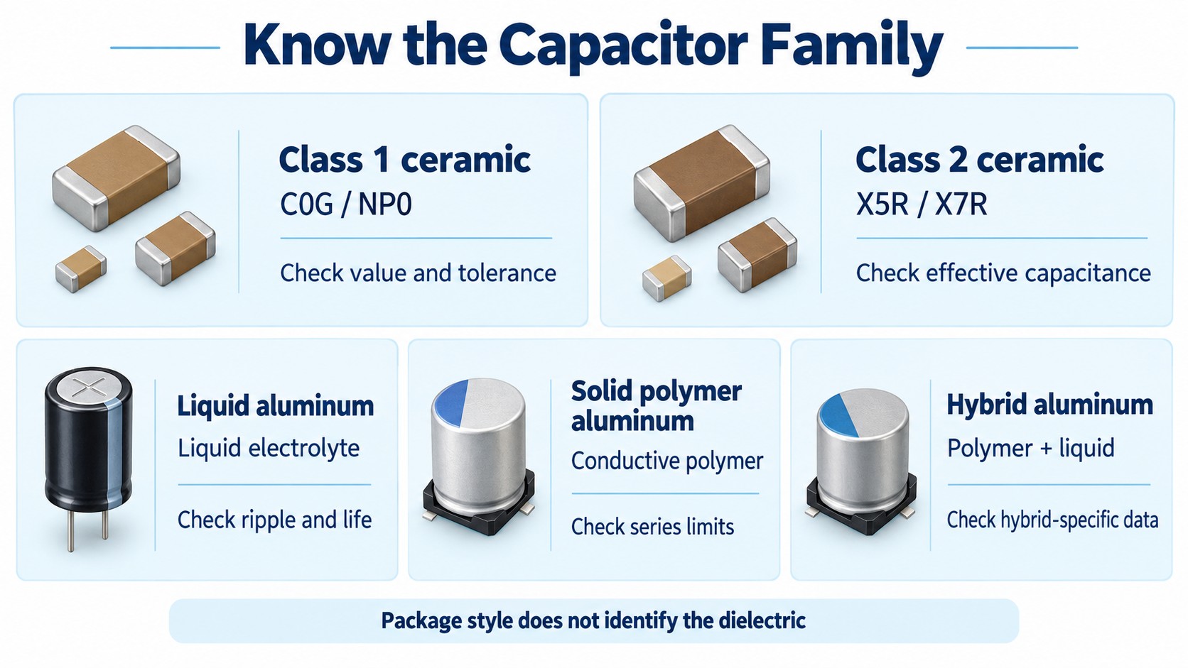
| Candidate family | Why it enters the shortlist | What still needs evidence |
|---|---|---|
| Class 1 ceramic, such as C0G/NP0 | Capacitance stability in a suitable value and package | Actual capacitance, tolerance, voltage and signal conditions |
| Class 2 ceramic, such as X5R/X7R | Compact capacitance for many decoupling and power applications | Effective capacitance under bias, temperature and age; mechanical and acoustic behavior |
| Liquid aluminum electrolytic | Bulk capacitance on a DC rail | Ripple, impedance, temperature, polarity and the applicable life model |
| Conductive-polymer aluminum solid | A low equivalent series resistance (ESR) option for suitable power rails | The exact series' voltage, ripple, life and polarity restrictions |
| Conductive-polymer hybrid aluminum | A construction combining polymer and liquid electrolyte | Hybrid-specific operating, waveform and life requirements |
The table identifies candidates, not a universal performance ranking. There is no useful blanket statement that every ceramic has better frequency response than every electrolytic, or that all aluminum parts share the same aging mechanism. Compare the actual series and mounted configuration.
Also separate package from technology. Surface mount does not mean ceramic, and through-hole does not mean electrolytic. A footprint, terminal arrangement or delivery form cannot establish the dielectric.
Check 1: Will enough capacitance remain in the circuit?
Compare the circuit's required capacitance with the candidate's capacitance under the conditions in which it will operate. A nominal value measured under the manufacturer's specified test conditions is a starting datum, not proof of the value available on an energized board.
DC bias and dielectric choice
High-permittivity MLCCs such as X5R and X7R can lose capacitance when DC voltage is applied. C0G-type temperature-compensating ceramics do not exhibit that same ferroelectric DC-bias behavior. Murata's DC-bias FAQ explains why the distinction matters.
For a Class 2 candidate, obtain its actual voltage-dependent characteristics. Then check temperature, tolerance and the measurement conditions. A higher voltage rating alone does not tell you which of two parts retains more capacitance at your operating voltage. Nor does the X7R designation, by itself, describe a part's DC-bias curve.
A productive comparison sheet has separate columns for nominal capacitance and the supported operating-condition estimate or limit. If only typical curves are supplied, label the result as an estimate. Do not silently turn a typical graph into a guaranteed minimum.
Aging and measurement history
Class 2 capacitance can also decrease with time on an approximately logarithmic time scale. This differs from electrolyte loss, and temperature-compensating ceramics do not have the same aging mechanism. Murata's capacitance-aging explanation also describes how sufficient heating can reset this aging before it resumes.
That makes measurement history relevant when comparing incoming inspection, a recently soldered board and an aged assembly. Use the manufacturer's conditioning and measurement procedure. Do not invent a universal aging rate or add unrelated worst-case percentages and call the result a guaranteed limit.
Worked example: a charge requirement
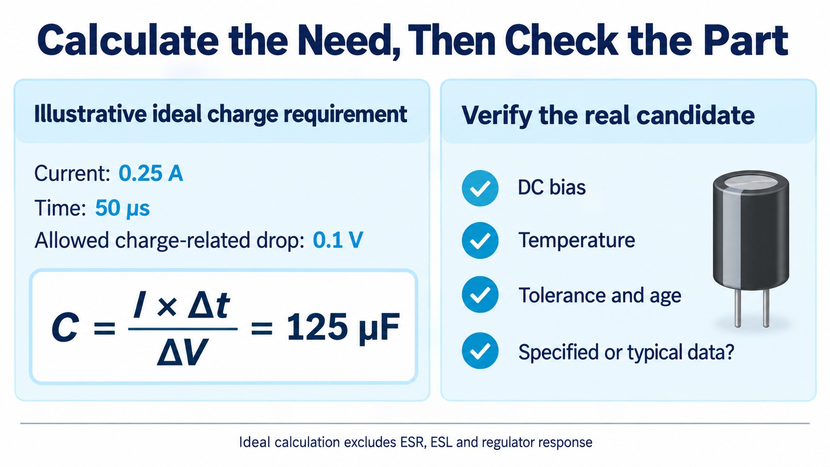
Assume, for illustration, that a capacitor alone supplies 0.25 A for 50 µs, and that the permitted voltage change caused by charge removal is 0.1 V. The constant-current, ideal-capacitor relationship gives:
Ccharge ≥ I × Δt / ΔV = 0.25 A × 50 µs / 0.1 V = 125 µF
This is an original calculation using stated assumptions, not a measured board or a specification for a particular capacitor. It says the ideal charge requirement is 125 µF of effective capacitance. It does not approve a nominal 125 µF part.
The calculation excludes ESR and inductive voltage effects, regulator response and variation with operating conditions. In a real design, allocate the permitted voltage excursion among those contributions. A regulator may supply some of the load current during the interval; conversely, interconnect inductance may make part of the capacitor bank ineffective during the fastest edge.
The practical output of this check is therefore a requirement with conditions: how much capacitance must be available, over which voltage and temperature range, and with what evidence margin. “Use more microfarads” is not a complete specification.
Check 2: Does the impedance fit the circuit and its control loop?
A capacitor must present a suitable impedance over the frequencies that matter. Its nominal capacitance cannot describe the entire frequency response, and an isolated component curve cannot describe every effect of mounting it on a board.
A simple lumped model includes equivalent series inductance (ESL):
Z(f) ≈ ESR(f) + j[2πfLESL − 1/(2πfC)]
This model explains the capacitive, series-resonant and inductive regions; it is not a substitute for the manufacturer's frequency data. ESR, capacitance and other losses can vary with conditions, and a real installed network can contain additional resonances.
For local decoupling, a short supply-and-return loop is part of the component choice. Package terminals, pads, vias and the route to the IC all affect the installed result. Our 100 nF decoupling capacitor guide develops that local-current-path problem in more detail.
Lower ESR can change regulator stability
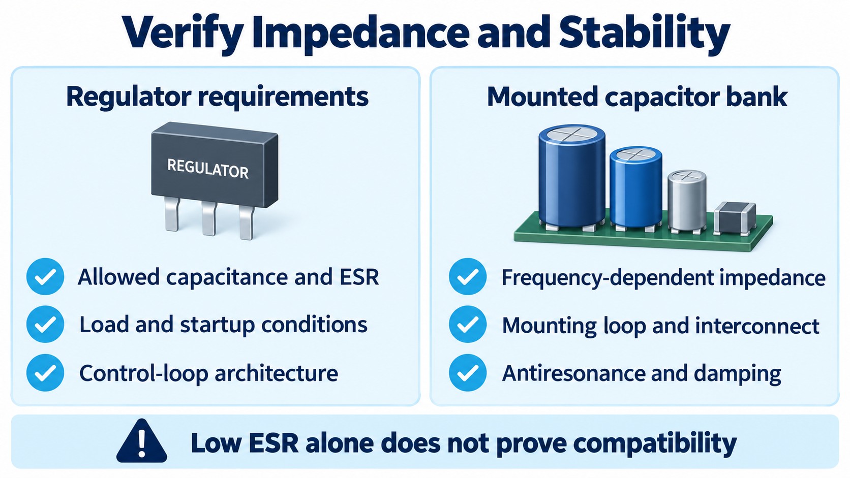
Check the regulator before replacing its output capacitor. Some LDO architectures depend on an ESR-related zero in the output network for compensation; substituting an extremely low-ESR MLCC can change loop stability. Other LDOs are designed for ceramic output capacitors. TI's AN-1482 on LDO stability explains the architectural distinction.
The acceptance criteria belong to the actual regulator and operating range. Record the permitted effective capacitance, ESR conditions, load range and any implementation restrictions. Do not copy a typical ESR window from an application note into every regulator design.
A quieter waveform at one load point does not prove stable operation across startup, light load, large load changes and temperature. Likewise, adding a resistor or another capacitor is a circuit change that needs its own justification.
Mixed capacitor banks need an impedance check
Using ceramic and electrolytic capacitors together can be useful, but it does not automatically create a smooth, low-impedance network. Wiring inductance and capacitors with different resonant behavior can produce antiresonance: a frequency region in which the combined impedance rises. Murata discusses both mounting inductance and this effect in its EMI suppression guidance.
Treat the bank and its interconnect as a network. Review where impedance peaks occur and whether the damping and layout suit the load. Do not assume that adding progressively smaller values always improves the result, or that mixed values must always be avoided.
This check closes when the capacitor network meets the relevant impedance and control requirements. A technology preference alone cannot close it.
Check 3: Can it carry ripple current for the required service life?
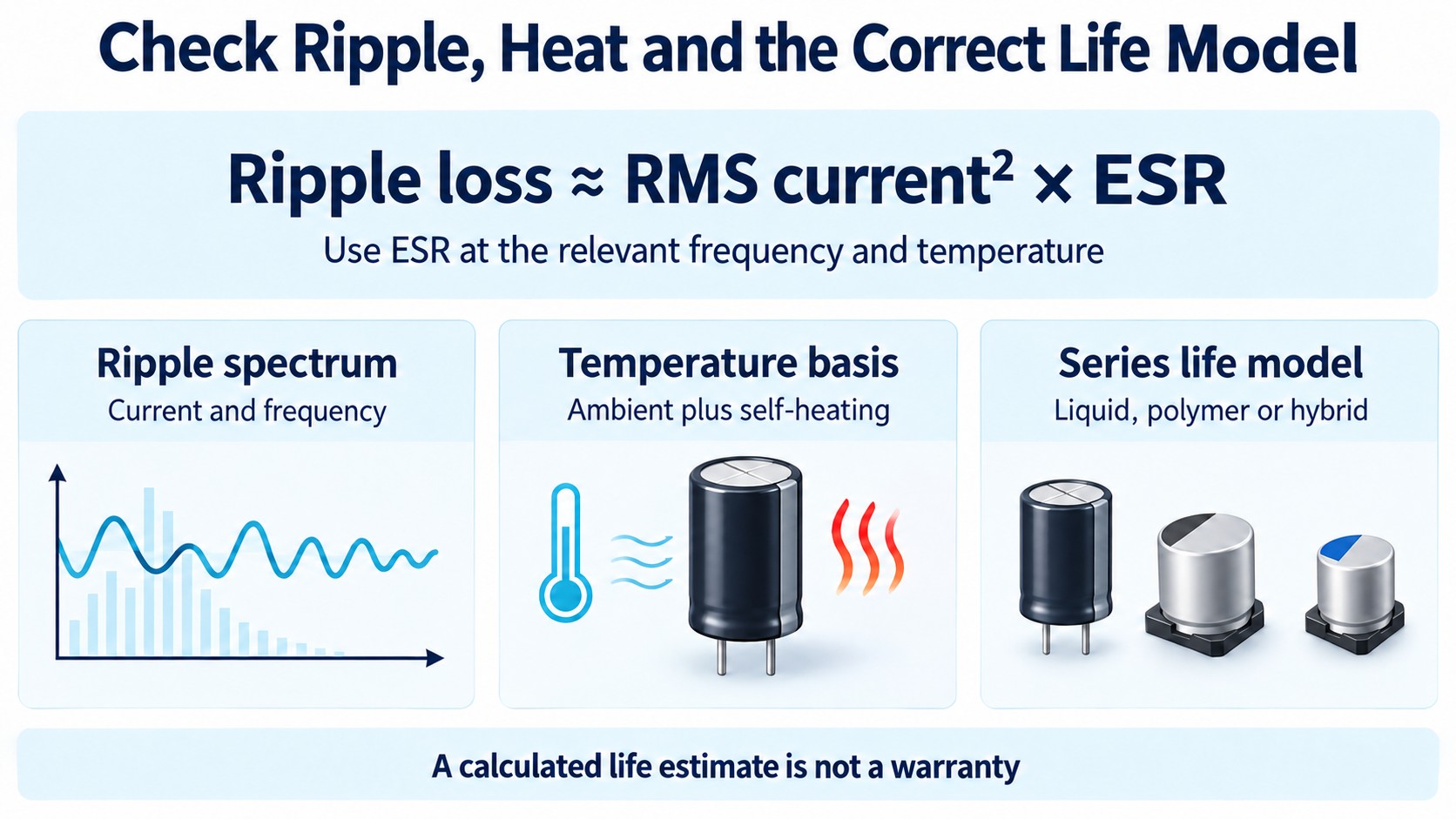
Ripple capability and life are operating-condition questions. Record the actual current waveform, frequency content and temperature rather than selecting a part from capacitance and voltage alone.
For a simplified loss estimate at a stated frequency and temperature:
Pripple ≈ IRMS2 × ESR
This approximation isolates ripple-related resistive loss. It does not include every loss mechanism. If current contains substantial components at different frequencies, use the frequency-dependent loss data or the manufacturer's conversion method rather than applying one arbitrary ESR number to the whole spectrum.
Liquid aluminum: include self-heating
For liquid aluminum electrolytics, electrolyte loss is an important wear mechanism, while ripple-related internal heating affects the temperature that drives degradation. Nippon Chemi-Con's liquid-aluminum lifetime FAQ describes the separate roles of ambient temperature, ripple heating and product construction.
A “hours at temperature” endurance entry is tied to stated test conditions and end-of-test criteria. It is not a promise that every installed capacitor will fail at that hour, or that a board will achieve a calculated service interval. Use the manufacturer's model for the applicable series and stay within its stated limits.
Avoid a universal temperature-doubling rule. A calculation that omits ripple heating, uses the wrong product model or extends beyond the model's permitted range can produce a reassuring number without establishing a suitable component.
Polymer and hybrid: use the correct model
Solid conductive-polymer aluminum capacitors are not exempt from wear or ripple heating. Chemi-Con's solid-polymer lifetime document describes degradation associated with the polymer for the listed series and places limits on lifetime estimation. Its equations are estimates for the specified products, not warranties for all polymer capacitors.
Hybrid aluminum parts also require their own series data. Their combination of liquid electrolyte and conductive polymer should not be described as an entirely liquid-free construction.
For procurement, the useful record is not simply “105°C, long life.” Record the exact series, endurance conditions, applied ripple assumptions, temperature basis and the document used for estimation. If those inputs are unknown, the life review remains open.
Check 4: Do polarity, mechanics and assembly permit the choice?
A part that passes the electrical comparison may still be unsuitable for the waveform, footprint or assembly process. Review the implementation independently rather than treating it as a final administrative check.
Polarity and the complete voltage waveform
Ordinary two-terminal MLCCs are nonpolar. Aluminum electrolytic candidates commonly require a defined polarity, including conductive-polymer products; special bipolar constructions must be identified explicitly.
Inspect DC voltage together with ripple peaks, startup, shutdown and possible reversals. A positive average voltage does not prove that a polarized capacitor never sees reverse voltage. Chemi-Con's hybrid capacitor precautions, for example, require the combined DC-plus-ripple peak to remain within rating and prohibit ripple that introduces reverse voltage.
Do not use that one document as the operating specification for every construction. Obtain the selected part's polarity, surge and waveform restrictions. A safety-rated AC application is a separate qualification task, discussed below.
Acoustic behavior is different from cracking
Ferroelectric MLCCs can turn electrical excitation into mechanical movement, producing audible board vibration. Mechanical excitation can also create an electrical response, which matters in sensitive signal paths. Murata's acoustic-noise FAQ explains these effects and notes that ordinary acoustic micro-vibration itself is not generally considered a capacitor reliability problem.
Audible noise, signal-path microphonics and a cracked ceramic body are therefore different observations. Do not diagnose a fracture merely because a capacitor sings, or conclude that an electrically working capacitor is acceptable in an acoustically sensitive product.
Board bending after soldering can cause a separate fracture mechanism. Murata's MLCC layout guidance identifies orientation and placement near board separation regions as factors affecting strain. Review the actual assembly, depanelization and mechanical-loading conditions; no universal clearance distance replaces that review.
Footprint and production details
Compare land pattern, terminal assignment, height, spacing, polarity marking and the selected manufacturer's assembly instructions. For can-style parts, include any specified vent clearance or mechanical support. Check the exact package drawing rather than choosing a replacement from an approximate photograph.
For a bank of MLCCs replacing one larger capacitor, count the pads, routing area, assembly operations and inspection access as well as the component bodies. Our SMT and through-hole selection guide explains how manufacturing and mechanical requirements affect the BOM decision.
Which capacitor suits each application?
Use the application to narrow the shortlist, then apply all four checks. These are starting directions, not approved values or substitutes.
| Circuit requirement | Reasonable starting candidate | Condition that can change the decision |
|---|---|---|
| Local digital-IC decoupling | MLCCs following the IC guidance | Effective capacitance, mounting loop and the IC's required network |
| DC-rail bulk support | Liquid aluminum, polymer, hybrid or a qualified MLCC bank | Charge requirement, space, ripple, impedance and required service life |
| Regulator output filtering | The construction permitted by the regulator | Effective capacitance, ESR window and loop behavior across operating conditions |
| Precision timing or a sensitive analog filter | A suitably specified Class 1 ceramic or another stable dielectric | Required value, signal amplitude, tolerance, drift and mechanical sensitivity |
| Board input subject to startup or cable events | A network qualified for the actual source and load | Inrush, overshoot, source impedance, voltage peaks and damping |
| AC-mains interference suppression | Purpose-designed, appropriately approved safety capacitors | The required X/Y function, AC rating and applicable system requirements |
Do not equate rectified-DC bulk storage with across-line interference suppression. Vishay's safety-capacitor overview distinguishes X and Y applications and includes purpose-designed film, ceramic-disc and MLCC technologies. A generic high DC-voltage rating or nonpolar construction does not establish that approval.
Similarly, “audio” is too broad to select a dielectric. A supply reservoir, coupling position and precision filter impose different requirements. Document the signal voltage and polarity, acceptable distortion or noise, and required capacitance before comparing candidate parts.
Can you replace one capacitor technology with another?
Sometimes, but approve the change against requirements rather than a pair of headline ratings. Replacing an electrolytic with ceramic may change effective capacitance, ESR, resonances, startup behavior and mechanical sensitivity. Replacing ceramic with electrolytic may change the local high-frequency path, polarity requirements and package.
A capacitor bank can be a valid redesign, but it is not automatically a drop-in replacement for one component. The changed layout and population need to be included in the approval record.
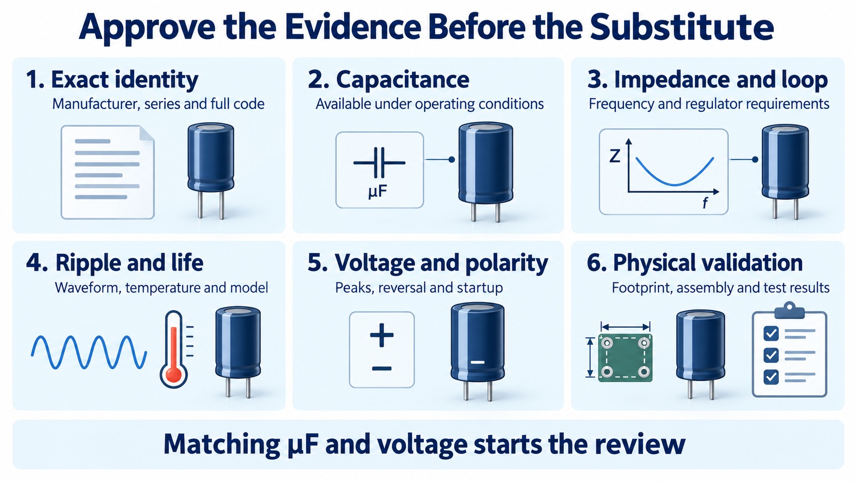
| Replacement gate | Evidence to retain | What should keep approval open |
|---|---|---|
| Identity | Manufacturer, complete ordering code, series and document revision | A family name or truncated part number |
| Capacitance | Required minimum or acceptable range under actual conditions | Only the nominal label or an unqualified typical estimate |
| Impedance and loop | Relevant frequency data and regulator requirements | An ESR comparison at one unrelated test frequency |
| Ripple and temperature | RMS waveform assumptions, frequency treatment and thermal basis | A ripple rating copied without its conditions |
| Life | Applicable series model, input conditions and estimate limitations | A generic hours number or universal multiplier |
| Waveform | DC level, peaks, reversal and startup/shutdown conditions | Average voltage only |
| Physical implementation | Approved footprint, clearances, polarity and assembly constraints | “Same size” based on a photograph |
| Validation | Defined acceptance limits and results for the changed configuration | A functioning prototype with no recorded test coverage |
This table is also a useful way to reject an overconfident substitution claim. “Equivalent capacitance” should trigger the next question: equivalent under which voltage, temperature, frequency and implementation conditions?
How should you compare two actual capacitor parts?
Give both candidates the same requirement sheet. If one datasheet reports impedance at a different frequency or ripple capability at a different temperature, do not place the numbers in the same column as though the conditions matched.
First extract the specified limits, test conditions and footnotes. Then add manufacturer-provided bias, frequency and thermal data. Mark typical curves, estimates and unverified assumptions distinctly. The datasheet-reading workflow shows how to preserve those distinctions in a component review.
Next define what the board test must resolve. Depending on the circuit, that may include supply ripple, load-step excursion, startup overshoot, temperature rise, regulator stability or audible noise. State operating corners and acceptance limits before testing; otherwise the result “looks good” is difficult to reproduce or approve.
Measurement conditions matter as well. State whether capacitance and ESR were measured in isolation or in-circuit, the instrument frequency and signal level, and any bias or conditioning. Nearby parallel paths can affect in-circuit readings. An unqualified bench reading should not overwrite a manufacturer's conditional specification.
Finally record one of three outcomes: meets the stated requirement, requires further evidence, or does not meet the requirement. That makes the decision usable by purchasing without making an engineering estimate look like an approved substitute.
What should a capacitor RFQ or BOM review include?
Send the complete manufacturer part number and approved series, not just “10 µF ceramic” or “470 µF electrolytic.” Include quantity, assembly package and delivery-form needs, required documentation, and whether alternatives are allowed.
For an alternative request, attach the four-check requirements: effective capacitance conditions, impedance and regulator constraints, ripple and temperature basis, life assumptions, waveform restrictions and physical limits. Specify who can approve a change to construction or layout.
Use the capacitor category to organize candidates, then submit the full BOM and capacitor requirements for an RFQ. Current stock, price, lead time and lot documentation require separate confirmation. A supplier's available option still needs to pass the technical acceptance criteria.
Frequently asked questions
Is a ceramic capacitor always better than an electrolytic?
No. Ceramic is often a useful candidate for compact local decoupling, while aluminum electrolytic technologies often enter a bulk-capacitance shortlist. The selected part must satisfy effective capacitance, impedance, ripple, life and implementation requirements. A technology name does not settle those checks.
Does choosing a higher voltage MLCC eliminate DC-bias loss?
No. The voltage rating is an operating limit, not a guarantee of capacitance retention. Compare the actual candidates' bias characteristics at the intended voltage, alongside the other applicable conditions.
Are polymer capacitors nonpolar or unlimited-life parts?
Do not assume either. Conductive-polymer aluminum products can be polarized and have series-specific operating and life restrictions. “Polymer” alone is insufficient to approve polarity, ripple or lifetime.
Can ceramic and electrolytic capacitors be connected in parallel?
Yes, when the resulting network suits the circuit. Review mounting inductance, impedance peaks, regulator requirements and current sharing over the relevant frequencies. The sum of nominal capacitances does not describe the complete network.
Is a matching capacitance and voltage enough for a replacement?
No. Those two ratings start the comparison. Effective capacitance, ESR and frequency behavior, regulator compatibility, ripple, life, polarity, footprint and assembly requirements can all change the result. Retain evidence and approval for the exact replacement configuration.
Technical sources reviewed October 16, 2026. The calculation uses illustrative assumptions, and the figures are conceptual educational graphics. No specific capacitor model, commercial availability or complete substitution is guaranteed by this guide.