Table of Contents
nPM1300 PMIC: A Practical Design Guide for Embedded Power Management
1. Product Summary
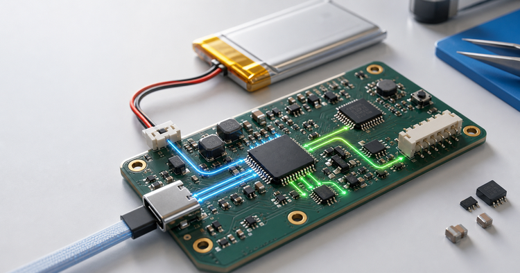
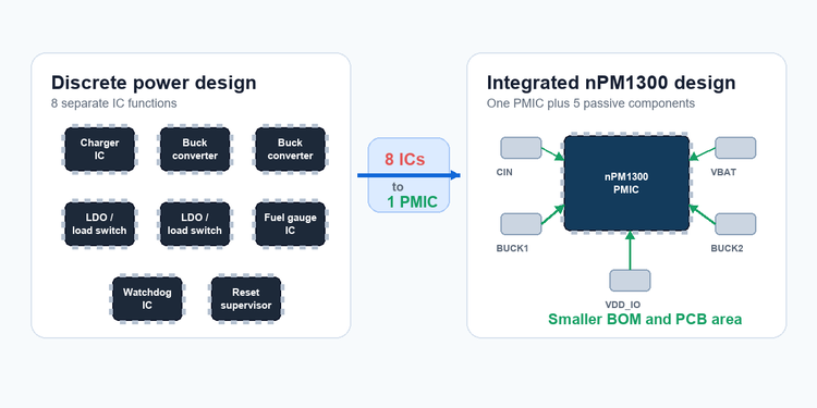
The nPM1300 is Nordic Semiconductor’s flagship Power Management IC. One chip replaces five to eight discrete components: a battery charger, two buck regulators, two LDOs or load switches, an algorithm-based fuel gauge, a hardware watchdog, hard-reset logic, and a power-loss warning circuit.
If you are designing a battery-powered device around an nRF52, nRF53, nRF54, or nRF91—or even a non-Nordic MCU like an STM32 or RP2040—the nPM1300 can shrink your BOM, simplify your PCB, and give you battery state-of-charge visibility without adding a separate fuel gauge IC.
Key numbers at a glance:
| Parameter | Value |
|---|---|
| Charger | Linear, up to 800 mA, JEITA-compliant |
| Buck regulators | 2×, 200 mA each, 1.0–3.3 V |
| LDO / load switch | 2×, 50 mA LDO or 100 mA switch |
| Fuel gauge accuracy | < 2% (algorithm-based) |
| Ship mode current | 370 nA |
| Hibernate mode current | 500 nA |
| Interface | I²C-compatible TWI |
| Packages | QFN32 5×5 mm / WLCSP 3.1×2.4 mm |
| Operating temperature | –40 °C to +85 °C |
2. Application Scenarios
Before diving into electrical specs, it helps to see where the nPM1300 actually fits. If none of these match your design, the rest of this article may not matter much.
With the use cases in mind, here are the key electrical specs that make—and sometimes limit—those applications possible.
2.1 BLE Sensor Nodes and Wearables
Paired with an nRF52 or nRF53 SoC, the nPM1300 handles the entire power path in a device that wakes up periodically, takes a sensor reading, pushes data over BLE, and goes back to sleep.
The ship mode (370 nA) keeps the battery from draining during storage or shipping. The hibernate mode (500 nA) lets the device sleep for weeks between charges while retaining register state. And the fuel gauge means a wearable can report its remaining battery percentage to the user—something voltage-only gauges get wrong by 20% or more in cold temperatures.
2.2 Cellular IoT Terminals
For an nRF91-based NB-IoT or LTE-M asset tracker, the nPM1300 runs from a single Li-Po cell and feeds the nRF91’s internal buck regulators through its unregulated output rail. The USB-C port detection (up to 1500 mA input current limit) means a single USB-C connector handles both charging and data—no separate USB controller IC needed.
The power-loss warning feature matters here: if the battery voltage drops below a programmable threshold, the nPM1300 fires an interrupt to the host MCU. The device has time to save critical telemetry data before the system shuts down.
2.3 Non-Nordic MCU Systems
The nPM1300 talks over standard I²C. It does not require a Nordic SoC.
If your design uses an STM32, an RP2040, or any other Arm Cortex-M controller with an I²C peripheral, you can read the nPM1300’s voltage, current, and temperature registers directly. A practical example: polling register 0x3A–0x3D on the nPM1300 returns the battery voltage as a 16-bit value in millivolts. From there, your firmware can estimate state of charge, trigger low-battery warnings, or log power telemetry.
The system management features—hardware watchdog, boot-failure recovery, hard reset—work regardless of what MCU is on the other side of the I²C bus. In a design prone to firmware lockups or brownout conditions, this is a meaningful reliability upgrade that would otherwise require extra supervisor ICs.
2.4 Consumer Rechargeable Devices
Gaming mice, TWS charging cases, and remote controls benefit from the nPM1300’s JEITA-compliant charging, three built-in LED drivers for battery indicators, and the dual-button hard-reset function. A gaming mouse can use one button for normal pairing and a long-press on both buttons to hard-reset the entire system—all handled by the PMIC without waking the host MCU.
The nPM1300 fits into a broader PMIC selection framework. See our [PMIC Selection Guide] for a cross-category comparison across automotive, industrial, IoT, and server PMIC options. (Coming soon)
3. Core Electrical Characteristics and Trade-offs
No PMIC does everything. The nPM1300 makes specific design choices. Here is where it excels, and where you might look elsewhere.
Charging System
Chemistry support: Li-ion, Li-Po, LiFePO₄ (single cell)
Charge current: programmable up to 800 mA, linear topology
Termination voltage: programmable 3.5–4.45 V
Thermal regulation: automatic, with programmable maximum die temperature
The linear charger keeps noise low and the BOM minimal—no inductor needed. The trade-off is efficiency: a linear charger dissipates (V_IN – V_BAT) × I_CHG as heat. If your input is 5 V USB and the battery sits at 3.6 V, charging at 800 mA burns about 1.1 W in the PMIC. For a small, sealed enclosure, this matters. If charge speed is less critical than noise and BOM simplicity—which is true for most BLE and IoT products—the linear topology is a sensible choice.
USB Port Detection
The nPM1300 automatically detects the connected USB source and sets the input current limit accordingly:
Standard downstream port: 100 mA
Standard USB host: 500 mA
USB-C with 1.5 A capability: 1500 mA
This removes the need for a separate USB port controller IC or current-sense resistor. Your firmware does not need to implement USB enumeration to get the right charge current. Another IC gone from the BOM.
Buck Regulators (×2)
Output: 1.0–3.3 V in 100 mV steps, 200 mA per channel
Automatic PWM/PFM mode switching for light-load efficiency
Forced PWM mode available when low noise matters more than light-load efficiency
200 mA is enough for a BLE SoC, a handful of sensors, and an external flash. It is not enough for a cellular modem’s transmit burst, a motor driver, or a high-current display. If your design pulls more than 200 mA on a single rail, you need an external regulator—or a different PMIC.
LDO / Load Switch Pins (×2)
Each pin can be configured as either an LDO (50 mA, 1.0–3.3 V) or a load switch (100 mA, passing through an external supply). This flexibility means you can power two low-noise analog rails or switch two external power domains with a single I²C command.
Unregulated System Rail
The nPM1300 provides an unregulated output that follows the battery or USB input voltage. This rail can supply up to 2 A from battery or 1.5 A from USB—useful for feeding an external high-current regulator or directly powering an nRF91 SiP’s internal bucks.
Power Modes
| Mode | Current | Wake-up | Use Case |
|---|---|---|---|
| Ship | 370 nA | Button long-press | Factory-to-end-user storage |
| Hibernate | 500 nA | Programmable timer | Long sleep between periodic wake-ups |
| Active | ~5 µA base | N/A | Normal operation |
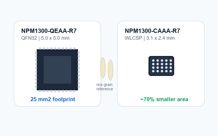
Package Options
| Ordering Code | Package | Size | Notes |
|---|---|---|---|
| NPM1300-QEAA-R7 | QFN32 | 5.0 × 5.0 mm | Hand-solderable with hot air, exposed thermal pad |
| NPM1300-CAAA-R7 | WLCSP | 3.1 × 2.4 mm | Reflow only, better for space-constrained designs |
Order the wrong suffix and the package will not fit the footprint. Double-check.
4. Deep Dive: Algorithm-Based Fuel Gauging
This is the feature that separates the nPM1300 from most PMICs in its class. And it is worth understanding how it works, because “fuel gauge” means very different things depending on the method.
4.1 Three Ways to Measure Battery Charge
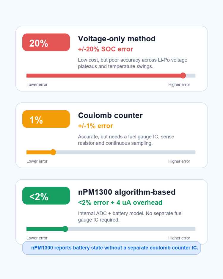
Voltage-only estimation is the simplest method. Measure the battery terminal voltage, map it to a pre-characterized discharge curve, and call that state of charge. The problem: a Li-Po battery’s voltage plateau is flat between roughly 20% and 80% SOC. A 50 mV measurement error—easy in a noisy system or across temperature swings—can translate to a 20% SOC error. In cold weather, the error gets worse.
Coulomb counting solves the accuracy problem by integrating charge current in and out of the battery. A dedicated fuel gauge IC with a sense resistor tracks every milliamp-second. Accuracy can reach ±1%. The trade-off: you add a dedicated IC, a precision sense resistor, and continuous ADC sampling that burns tens of microamps. For a BLE sensor node that averages 10 µA in sleep, a 50 µA coulomb counter more than triples the system’s power budget.
The nPM1300’s algorithm-based approach sits between these two. It measures voltage, current, and temperature through its internal ADC—adding roughly 4 µA to the PMIC’s baseline consumption—and runs a battery model that correlates these readings to state of charge. The result: accuracy within 2% without the hardware cost of a coulomb counter.
4.2 Building a Battery Model
The nPM1300 does not ship with a built-in battery model. You need to generate one for your specific battery.
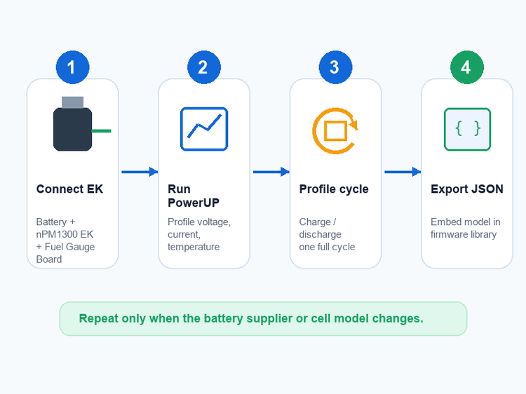
The workflow:
Connect your battery to the nPM1300 Evaluation Kit (EK) + nPM Fuel Gauge Board
Open the nPM PowerUP app in nRF Connect for Desktop
Run a charge/discharge cycle. The tool profiles the battery’s voltage, current, and temperature behavior
Export the model as a .josn file
Embed the model in your firmware alongside the nrf_fuel_gauge library
Once the model is loaded, the library handles the rest. You do not need to repeat this process per production unit—only when you change battery suppliers or cell models.
4.3 What the Fuel Gauge Outputs
The nrf_fuel_gauge library provides four metrics:
State of Charge (SOC): 0–100%, the number most products show to the user
State of Health (SOH): estimates how much of the original capacity remains as the battery ages
Time to Empty (TTE): predicted runtime at the current load
Time to Full (TTF): predicted time until the battery reaches 100%
4.4 Firmware Integration Notes
For Nordic SoCs, the nrf_fuel_gauge library is part of the nRF Connect SDK. Integration is mostly a matter of including the library, loading the battery model, and calling the update function at regular intervals—typically once per second. For a hands-on walkthrough of the evaluation process, see the Element14 RoadTest review, which covers the nPM1300 EK setup, nPM PowerUP configuration, and fuel gauge accuracy testing in detail.
For third-party MCUs, the integration path is less polished. You read voltage (register 0x3A–0x3D), current (0x3E–0x41), and temperature (0x42–0x43) over I²C, then feed them into your own algorithm or a ported version of Nordic’s library. This is not a showstopper, but budget time for it.
A note on SDK versions: early adopters using nRF Connect SDK v2.6.0 reported SOC drift during charging, where the fuel gauge would increment roughly 1% per second regardless of actual charge progress. Nordic acknowledged this as a known issue and addressed it in a subsequent fuel gauge library update. If you are using an older SDK version, check the release notes for the nrf_fuel_gauge module and update before tuning your battery model.
Integrating the nPM1300 into your design? Request a quote for NPM1300-QEAA-R7 or NPM1300-CAAA-R7 →
5. Deep Dive: System Management Features
Beyond power regulation, the nPM1300 includes several features that in a discrete design would require separate ICs. Understanding what each one replaces puts the BOM savings in perspective.
5.1 Hard Reset
The nPM1300 supports single-button or dual-button hard reset. The reset is off by default at power-up—your firmware must explicitly enable it over I²C—which prevents accidental resets during boot or configuration.
In a discrete design, you would need a dedicated reset supervisor IC plus debounce circuitry for the button(s). With the nPM1300, the PMIC handles both. A long-press on the configured button(s) cuts power to the system rails and restarts the MCU cleanly, even if the MCU firmware is completely unresponsive.
5.2 Watchdog and Boot-Failure Recovery
The nPM1300’s system-level watchdog is independent of the host MCU’s internal WDT. If the host stops toggling the watchdog within the configured timeout window, the PMIC initiates a full power-cycle reset.
The boot-failure recovery adds another layer: if the MCU fails to boot successfully N consecutive times, the nPM1300 can enter a safe state—for example, keeping the system powered off until a manual reset—instead of looping indefinitely.
In a discrete design, this requires an external watchdog IC plus sequencing logic. The nPM1300 collapses that into one register setting.
5.3 Power-Loss Warning
When the VBUS supply is removed or the battery voltage falls below a programmable threshold, the nPM1300 asserts an interrupt. The host MCU can use this warning window—typically milliseconds to seconds, depending on the load and battery capacity—to save critical data before shutdown.
For a remote IoT device that logs sensor data locally, this one feature can prevent data loss during unexpected power failure.
5.4 Power Mode Management
Ship mode (370 nA): the device is essentially off. Only a button press can wake it. Use this for factory-to-end-user transit.
Hibernate mode (500 nA): the PMIC shuts down most internal blocks but keeps a programmable wake-up timer running. Use this for devices with long sleep intervals.
Both modes eliminate the need for an external load switch to disconnect the battery during storage.
6. Design Considerations
6.1 PCB Layout
QFN32 version (QEAA-R7): the 5×5 mm package has a large exposed thermal pad on the bottom that must be soldered to a ground plane for heat dissipation. Hand-soldering is possible with a hot-air station and solder paste, but it is not a job for a basic soldering iron. If you are hand-assembling prototypes, order a stencil.
WLCSP version (CAAA-R7): 3.1×2.4 mm, ball-grid array. Reflow only. The space savings are real—this is nearly 70% smaller than QFN32—but prototyping is harder. Pick your package based on your assembly method, not just the datasheet drawing.
For both packages: place the BUCK input and output capacitors as close to the PMIC pins as possible. Minimize the power loop area. The nPM1300 EK layout is a reasonable reference.
6.2 Minimum BOM
In theory, the nPM1300 can operate with as few as five external passive components:
VDD_IO bypass capacitor
BUCK1 output capacitor
BUCK2 output capacitor
VBUS input capacitor
Battery terminal capacitor
In practice, most designs add:
An NTC thermistor for battery temperature monitoring during charging (required for JEITA-compliant charging profiles)
Current-limiting resistors for the LED drivers
I²C pull-up resistors (may be internal if the MCU is on the same board and supports them)
6.3 I²C / TWI Notes
The nPM1300 uses an I²C-compatible Two-Wire Interface. It operates at standard (100 kHz) and fast (400 kHz) speeds. If the MCU is on the same PCB, the internal pull-ups may suffice. If the nPM1300 is on a separate board connected via a cable harness, add external pull-up resistors and keep the bus capacitance low.
The PMIC’s I²C registers are documented in the nPM1300 datasheet. The address is fixed; check the datasheet for your specific variant.
7. Comparison and Cross-Reference
7.1 nPM1300 vs nPM1100
These are Nordic’s two PMICs, but they target different use cases.
8. Datasheet and Ordering Information
| nPM1100 | nPM1300 | |
|---|---|---|
| Buck regulators | 1×, 150 mA | 2×, 200 mA each |
| LDO / load switches | None (VOUT is selectable LDO or load switch) | 2× configurable |
| Fuel gauge | No | Yes, algorithm-based, < 2% |
| System management | No | Hard reset, WDT, boot recovery, power-loss warning |
| LED drivers | No | 3× |
| Software configuration | Not required | Required (I²C) |
| Best for | Cost-sensitive designs, quick prototyping | Products needing battery status, system reliability |
The short version: if you just need to charge a battery and power one rail, the nPM1100 is simpler and cheaper. If your product reports battery percentage to the user, needs a watchdog, or runs multiple voltage rails, the nPM1300 saves more BOM cost than the per-unit price difference suggests.
For a full, side-by-side comparison, see our nPM1100 vs nPM1300 guide. (Coming soon)
7.2 nPM1300 vs Discrete Solution
| Discrete design | nPM1300 | |
|---|---|---|
| Charger IC | 1× | Built-in |
| Buck converters | 2× external ICs | Built-in (2×) |
| LDOs | 2× external ICs | Built-in (2×) |
| Fuel gauge | 1× IC + sense resistor | Built-in (algorithmic) |
| Watchdog IC | 1× | Built-in |
| Reset supervisor | 1× | Built-in |
| USB port controller | 1× | Built-in |
| Total ICs | ~7–9 | 1 |
| PCB area | Significantly larger | QFN32: 25 mm²; WLCSP: ~7 mm² |
| Design effort | Each IC requires separate qualification and layout | Single datasheet, single layout |
The development time difference is harder to quantify but real: getting a discrete charger, fuel gauge, watchdog, and reset sequence to play together takes days of datasheet cross-referencing, layout tuning, and bring-up debugging. The nPM1300 eliminates that integration work.
7.3 Alternative PMICs
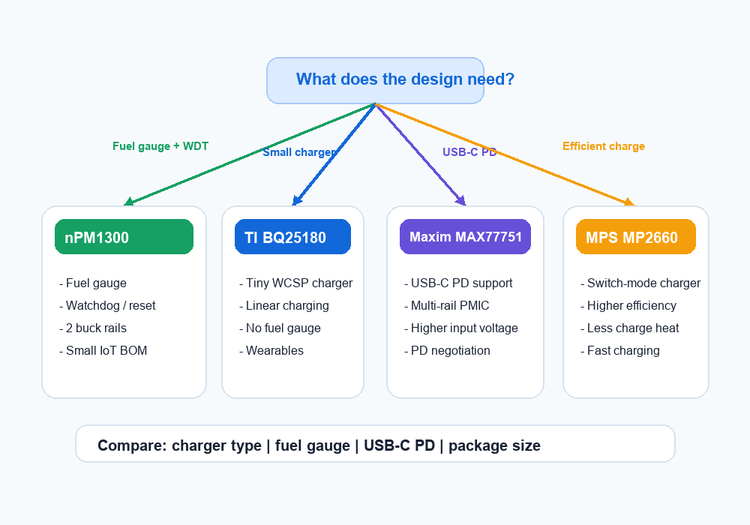
If the nPM1300 does not match your requirements, here are alternatives worth evaluating. None are drop-in replacements—always check pinouts and electrical ratings.
| PMIC | Key Difference | Better For |
|---|---|---|
| TI BQ25180 | Ultra-small WCSP, linear charger, no fuel gauge, no system management | Space-constrained wearables where battery reporting is not needed |
| Maxim MAX77751 | USB-C PD support, multi-rail | USB-C-powered devices requiring Power Delivery negotiation |
| MPS MP2660 | Switch-mode charger, higher efficiency at high charge currents | Fast-charging applications where heat dissipation matters |
Functional similarity does not imply pin-to-pin compatibility. Always cross-check pinouts and electrical ratings against the official datasheet before substitution.
| Parameter | Value |
|---|---|
| Manufacturer | Nordic Semiconductor |
| Part Numbers | NPM1300-QEAA-R7 (QFN32) / NPM1300-CAAA-R7 (WLCSP) |
| Package | 32-QFN 5×5 mm / WLCSP 3.1×2.4 mm |
| Interface | GPIO, I²C (TWI) |
| Battery Chemistry | Li-Ion, Li-Polymer, LiFePO₄ |
| Cells | 1 |
| Fault Protection | Over-current, over-temperature, over/under-voltage |
| Operating Temperature | –40 °C to +85 °C (TA) |
9. FAQ
Can I use the nPM1300 with a non-Nordic MCU?
Yes. The nPM1300 communicates over standard I²C (TWI), which works with any MCU that has an I²C peripheral—STM32, RP2040, ESP32, and others. You read voltage, current, and temperature registers directly over the bus. The fuel gauge algorithm is the only part that requires extra work: Nordic provides the nrf_fuel_gauge library for their SDK, but for third-party MCUs you need to implement your own state-of-charge logic or port the library.
What is the difference between NPM1300-QEAA-R7 and NPM1300-CAAA-R7?
These are the same chip in two different packages. QEAA-R7 is QFN32 (5×5 mm), hand-solderable with hot air. CAAA-R7 is WLCSP (3.1×2.4 mm), reflow-only. The WLCSP version is about 70% smaller but harder to prototype with. Order the wrong suffix and the footprint will not match your PCB.
Does the nPM1300 support USB-C Power Delivery (PD)?
No. The nPM1300 detects a USB-C connection and sets the input current limit to 1500 mA, but it does not negotiate PD voltage levels. The input voltage must stay within 4.0–5.5 V. If your design needs USB-C PD (e.g., 9 V or 12 V input), consider the Maxim MAX77751 or a discrete USB PD controller paired with a different PMIC.
How do I generate a battery model for the fuel gauge?
You need the nPM1300 Evaluation Kit, the nPM Fuel Gauge Board, and the nPM PowerUP desktop app. Connect your battery to the hardware, run a charge/discharge cycle through the app, and export the resulting .josn model file. Embed this file in your firmware alongside the nrf_fuel_gauge library. You only need to redo this when you change battery suppliers or cell models—not per production unit.
Can I drop an nPM1300 into a PCB designed for the nPM1100?
No. The nPM1100 and nPM1300 have different pinouts, different package options, and different I²C register maps. They are not pin-to-pin compatible. If you need a simpler PMIC without fuel gauge or system management, the nPM1100 may be a better fit—but it requires a separate PCB layout.
What happens when the battery is completely drained?
The nPM1300 enters ship mode at 370 nA. A long-press on the configured reset button wakes it. If the battery voltage drops below the minimum operating threshold (2.4 V), the PMIC shuts down entirely and will not restart until an external supply is connected or the battery recovers above the threshold.
Is the nPM1300 suitable for automotive applications?
The operating temperature range is –40 °C to +85 °C, which covers most non-safety-critical automotive environments (infotainment, telematics, body electronics). However, the nPM1300 is not AEC-Q100 qualified and does not meet functional safety standards (ISO 26262). For ADAS or safety-critical automotive systems, look at automotive-grade PMICs from TI, Infineon, or ST.
How long can a device run in hibernate mode on a single charge?
It depends on the battery capacity. In hibernate mode, the nPM1300 draws approximately 500 nA. A 200 mAh Li-Po cell would theoretically last about 45 years at that current—but in practice, the battery’s self-discharge rate (typically 2–5% per month) dominates. For practical designs, hibernate mode means the PMIC itself is not the limiting factor for shelf life.
Do I need to write firmware for the nPM1300?
Not for the PMIC itself—it has no programmable core. But you do need to configure it over I²C from your host MCU: set the regulator output voltages, enable the charger, configure the watchdog timeout, and enable the fuel gauge. Nordic’s nRF Connect SDK provides drivers and samples. For a quick start without writing code, the nPM PowerUP desktop app lets you configure all settings through a GUI and export a devicetree overlay.
What is the typical lead time for nPM1300 orders?
Lead times vary by package variant, order volume, and regional distributor stock. The QFN32 version (QEAA-R7) is generally more available than the WLCSP version (CAAA-R7), but supply tightened in some regions during Q3 2025 due to increased demand from BLE wearable manufacturers. For current stock status and delivery estimates, submit an inquiry → with your target quantity and we will respond with availability within one business day.
Need a quote for nPM1300-QEAA-R7 or nPM1300-CAAA-R7? Submit an inquiry →
Sourcing a full BOM? We can help with multi-line component procurement. Upload your BOM →

Alice lee
Business Manager
Focused on the electronic components sector, the author shares industry knowledge, product insights, and sourcing perspectives related to modern electronics manufacturing. With close attention to market trends, component applications, and supply chain developments, the content is designed to support engineers, buyers, and businesses in making more informed decisions.