
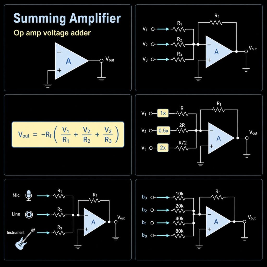
A summing amplifier is an op amp circuit that combines two or more input signals into one output. The most common form is the inverting summing amplifier, where each input enters the inverting node through its own resistor and the feedback resistor converts the total input current into an output voltage.
The circuit can perform direct addition, weighted addition, offset injection, audio mixing, sensor signal combination, and simple analog computation. The resistor ratios set how strongly each input contributes to the output, while the op amp determines the practical limits for supply voltage, input range, output swing, bandwidth, slew rate, noise, bias current, and load drive.
If your goal is only to average several signals with resistors, see the Passive Averager guide. A passive averager and an active summing amplifier are related, but the active circuit adds buffering, gain control, output drive, and more flexible weighting.
Quick Summary
| Item | Practical Answer |
|---|---|
| Main function | Combines several input voltages into one output |
| Most common topology | Inverting summing amplifier |
| Ideal formula | Vout = -Rf x (V1/R1 + V2/R2 + ... + Vn/Rn) |
| Equal input resistors | Vout = -(Rf/R) x (V1 + V2 + ... + Vn) |
| Unity-weight case | If Rf = R1 = R2 = ..., each channel has a magnitude weight of 1 |
| Weighted addition | Each input weight is approximately Rf/Rn in the ideal inverting circuit |
| Positive sum option | Use a non-inverting summing network or add another inversion stage |
| Main practical risks | Output clipping, incorrect biasing, noise, resistor errors, insufficient bandwidth, and load problems |
What Is a Summing Amplifier?
A summing amplifier is an operational-amplifier circuit that produces an output from the algebraic combination of several input voltages. In an inverting summer, each source is connected to the inverting input through an individual resistor. The non-inverting input is tied to ground in a dual-supply design or to a reference voltage in many single-supply designs.
Negative feedback keeps the inverting node close to the reference voltage while the circuit is operating linearly. Because the op amp input current is very small compared with the resistor currents, the currents from the input channels combine at the summing node and flow through the feedback network.
This makes the circuit more flexible than a simple resistor junction. Each channel can have a different gain coefficient, and the op amp provides isolation between the summing node and the load connected to the output.
Inverting Summing Amplifier Formula
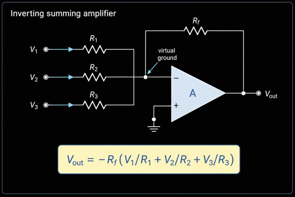
For the ideal inverting summing amplifier with the non-inverting input referenced to 0 V:
Vout = -Rf x (V1/R1 + V2/R2 + V3/R3 + ... + Vn/Rn)The negative sign shows that the output polarity is inverted relative to the weighted input sum. The contribution from each channel is determined by its resistor ratio:
Channel weight = Rf / RnFor example, with Rf = 100 kOhm:
| Input Resistor | Magnitude Weight |
|---|---|
100 kOhm | 1.0 |
200 kOhm | 0.5 |
50 kOhm | 2.0 |
The ideal formula is valid only while the op amp remains inside its linear input and output ranges. If the calculated output requires more voltage than the supply rails and output stage can provide, the real output clips.
Equal-Resistor Summing Amplifier
If all input resistors have the same value:
R1 = R2 = R3 = ... = Rthe equation simplifies to:
Vout = -(Rf/R) x (V1 + V2 + V3 + ... + Vn)If the feedback resistor is also equal to the input resistors:
Rf = Rthen:
Vout = -(V1 + V2 + V3 + ... + Vn)This is a unity-weight inverting adder. It is simple to calculate, but the output headroom still has to be checked. Several individually safe input signals can create a summed output that exceeds the available supply range.
Worked Example: Three-Input Weighted Summer
Assume:
| Input | Voltage | Input Resistor | Feedback Resistor | Weight |
|---|---|---|---|---|
V1 | 0.20 V | 100 kOhm | 100 kOhm | 1 |
V2 | 0.50 V | 200 kOhm | 100 kOhm | 0.5 |
V3 | -0.10 V | 50 kOhm | 100 kOhm | 2 |
Vout = -(1 x 0.20 V + 0.5 x 0.50 V + 2 x -0.10 V)
Vout = -(0.20 V + 0.25 V - 0.20 V)
Vout = -0.25 V
The example shows why a summing amplifier is useful: every channel can have an independent coefficient without needing a separate gain stage for each input.
Weighted Summing Amplifier
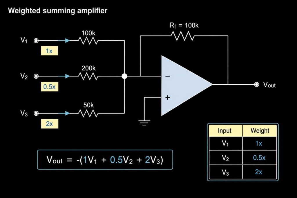
A weighted summing amplifier uses unequal input resistors to control how much each signal contributes to the output.
| Design Goal | Resistor Approach | Result |
|---|---|---|
| Equal contribution | Use equal input resistors | Each channel has the same weight |
| Increase one channel | Use a smaller input resistor | That channel contributes more current |
| Reduce one channel | Use a larger input resistor | That channel contributes less current |
| Set a specific coefficient | Choose approximately Rn = Rf/coefficient | Creates the required magnitude weight |
| Calibration adjustment | Use a fixed resistor with a controlled trim element | Allows coefficient adjustment but adds drift and process considerations |
The resistor ratios define the ideal coefficients. The absolute resistor values affect source loading, thermal noise, input-bias-current error, leakage sensitivity, and power consumption.
Non-Inverting Summing Amplifier
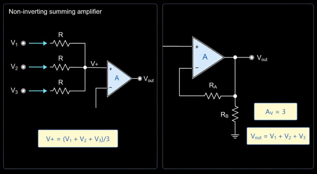
A summing function can also be built at the non-inverting input. With equal input resistors, low source impedances, and negligible op amp input current, the input node is approximately the average of the applied source voltages:
V+ = (V1 + V2 + ... + Vn) / nIf the non-inverting closed-loop gain is set to n, the ideal output becomes:
Vout = V1 + V2 + ... + VnIf the amplifier is used as a unity-gain buffer, the output follows the average instead of the sum. For a deeper explanation of the gain stage itself, see the Non-Inverting Operational Amplifier guide.
For unequal source resistances or weighted non-inverting networks, the node equation must include the actual resistor values and source impedances. Do not apply the simple arithmetic-average equation automatically.
Summing Amplifier vs Passive Averager
| Feature | Summing Amplifier | Passive Averager |
|---|---|---|
| Active device | Uses an op amp | Uses resistors only |
| Gain control | Can provide gain, attenuation, inversion, and weighting | Normally provides passive averaging or weighted division |
| Output drive | Op amp can buffer the load within its output limits | Output impedance depends on the resistor network and load |
| Channel interaction | Inverting summing node gives strong channel isolation in the ideal model | Sources can interact through the resistor network |
| Best fit | Active mixing, controlled weighting, offset addition, analog computation | Simple low-cost averaging where loading is acceptable |
For resistor-only averaging calculations and loading checks, see the Passive Averager guide.
Application 1: Audio Mixer
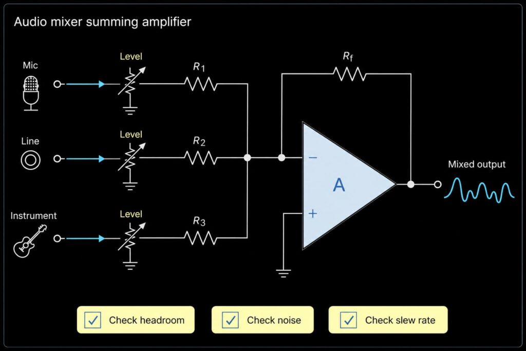
An audio mixer is a common summing-amplifier application. Several channels can feed individual resistors into one summing node, producing a mixed output before the next buffer, filter, or power stage.
| Check | Why It Matters |
|---|---|
| Headroom | The combined signal can clip even when each input is individually safe |
| Noise | Op amp voltage noise and resistor noise affect low-level channels |
| Distortion | Audio stages need suitable linearity over the expected signal range |
| Slew rate | Large high-frequency signals need sufficient output speed |
| Input coupling | AC coupling may be needed when sources carry different DC offsets |
| Output drive | The next stage must not overload the summing amplifier |
Application 2: Sensor Offset and ADC Signal Conditioning
A summing amplifier can add a reference voltage to a sensor signal so a bipolar or offset signal fits the input range of a single-supply ADC. In this application, the circuit has to be analyzed around the reference voltage rather than assuming the non-inverting input is at ground.
Important checks include:
- Input common-mode range over the full sensor range.
- Output swing at minimum and maximum sensor input.
- Reference-voltage noise and accuracy.
- Op amp offset voltage and drift.
- Input bias-current error through the resistor network.
- ADC input loading and sampling behavior.
For precision measurement, a low-offset or zero-drift op amp may be more important than a generic low-cost device.
Application 3: Binary-Weighted DAC
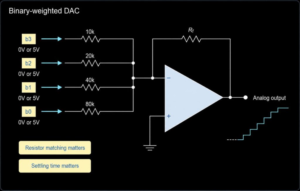
A binary-weighted DAC can be demonstrated by feeding digital logic levels into a summing amplifier through resistors whose values increase by powers of two.
| Bit | Example Input Resistor | Relative Contribution |
|---|---|---|
| MSB | 10 kOhm | Highest |
| Bit 2 | 20 kOhm | 1/2 of MSB |
| Bit 1 | 40 kOhm | 1/4 of MSB |
| LSB | 80 kOhm | Lowest |
This is useful for explaining DAC principles, but a discrete binary-weighted network becomes difficult to keep accurate as resolution increases. Resistor ratio error, digital output-voltage variation, switching glitches, and op amp settling all contribute to conversion error. Production designs that need predictable accuracy usually use a dedicated DAC or a precision resistor network.
Application 4: Weighted Analog Control
Control systems can use a summing amplifier to combine command, feedback, trim, offset, and limiting terms into one analog control signal.
For example:
Vout = -(1.0 x Vcommand + 0.25 x Vtrim + 0.5 x Vlimit)With Rf = 100 kOhm, magnitude coefficients can be created with approximately:
| Signal | Coefficient | Input Resistor |
|---|---|---|
Vcommand | 1.0 | 100 kOhm |
Vtrim | 0.25 | 400 kOhm |
Vlimit | 0.5 | 200 kOhm |
If a term needs the opposite sign, that polarity has to be created explicitly using the signal source, another inverting stage, a differential stage, or a different circuit architecture. A resistor value itself cannot be negative.
How to Choose Resistor Values
| Resistor Range | Benefit | Trade-Off |
|---|---|---|
| Lower values | Lower thermal noise and smaller bias-current voltage error | Higher source loading and current consumption |
| Moderate values | Often a practical balance for low- and medium-speed circuits | Still requires noise, loading, and bias-current checks |
| Higher values | Lower current draw and lighter source loading | More thermal noise, leakage sensitivity, and bias-current error |
| Precision matched network | Better coefficient matching and thermal tracking | Higher cost and package constraints |
Values in the tens-of-kilohms range are common starting points, but there is no universal resistor value. Source impedance, input bias current, noise, bandwidth, power budget, PCB leakage, and the required coefficient accuracy should determine the final choice.
Op Amp Selection Checklist
| Datasheet Item | Why It Matters |
|---|---|
| Supply voltage range | The op amp must operate from the board rails |
| Input common-mode range | Important for single-supply and non-inverting summing circuits |
| Output swing | The combined signal must stay within the output range under load |
| Gain bandwidth product | Closed-loop accuracy requires enough loop gain at the signal frequency |
| Slew rate | Limits large-signal output speed |
| Input offset voltage | Creates output offset and precision error |
| Input bias current | Produces error through input and feedback resistors |
| Noise | Important in audio, sensor, and high-gain circuits |
| Output current and load stability | The next stage must not cause clipping or instability |
| Package and pinout | Required for PCB compatibility |
| Temperature and lifecycle | Required for production and replacement decisions |
Common Mistakes
Mistake 1: Forgetting the Output Polarity
The common inverting summer produces the negative weighted sum. If the next stage requires the same polarity, use another inversion stage or a suitable non-inverting summing topology.
Mistake 2: Ignoring Output Headroom
The output is based on the combined contribution of all channels. Several moderate inputs can force the output beyond the available rails.
Mistake 3: Ignoring Resistor Ratio Error
In a weighted summer, resistor-ratio error directly changes the coefficients. Precision measurement and DAC-style applications often need tighter matching than a general-purpose mixer.
Mistake 4: Using High Resistor Values Without Checking Bias Current and Leakage
High resistor values reduce source loading but increase thermal noise and sensitivity to input bias current, board contamination, humidity, and leakage.
Mistake 5: Assuming One Op Amp Fits Every Summing Application
Audio, sensor, control, and DAC-related circuits prioritize different parameters. Noise and distortion may dominate in audio, while offset and drift may dominate in precision sensor circuits.
Related Op Amp Guides
- Inverting Operational Amplifier for the core circuit used by the most common summing topology.
- Non-Inverting Operational Amplifier for positive-gain and high-input-impedance configurations.
- Passive Averager for resistor-only averaging and loading analysis.
- Operational Amplifier Building Blocks for a wider comparison of common op amp circuits.
- Operational Amplifiers Summary for selection factors and BOM review.
- Operational Amplifier ICs for part-number sourcing and product review.
FAQ
What is a summing amplifier?
A summing amplifier is an op amp circuit that combines several input signals into one output. Depending on the topology and resistor ratios, the output can represent an inverted sum, a weighted sum, a positive sum, or an average.
What is the formula for an inverting summing amplifier?
For the ideal circuit referenced to 0 V, the formula is Vout = -Rf x (V1/R1 + V2/R2 + ... + Vn/Rn).
Why is the output of an inverting summing amplifier negative?
The input currents meet at the op amp's inverting node. Negative feedback drives the output with the opposite polarity required to balance those currents through the feedback resistor.
Can a summing amplifier produce a positive sum?
Yes. A non-inverting summing network can produce a positive result, or an inverting summer can be followed by another inverting stage.
Is a summing amplifier the same as a passive averager?
No. A passive averager uses resistors only and is affected directly by source and load impedances. A summing amplifier uses an active op amp stage and can provide gain, buffering, weighting, inversion, and output drive.
Can LM358 or LM324 be used in a summing amplifier?
They can be suitable in some low-speed applications, but suitability depends on supply voltage, input common-mode range, output swing, bandwidth, slew rate, offset, bias current, load, package, and the exact manufacturer datasheet.
Request Quote or Submit BOM
For a summing-amplifier design, include the exact op amp part number if known, package, quantity, supply rails, input signal range, frequency range, output load, and required accuracy.
Use Send Inquiry for known part numbers or a multi-line BOM. Stock, price, lead time, lifecycle, compliance, and replacement suitability should be verified during the quote review.