
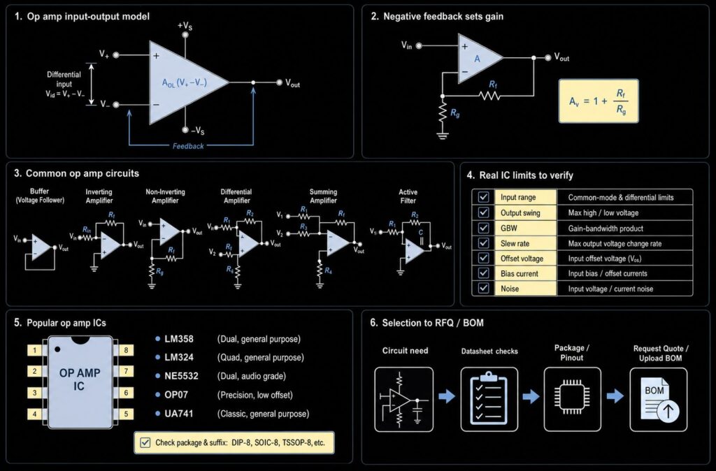
Operational amplifiers, usually called op amps, are analog ICs that amplify the voltage difference between two input pins and drive one output pin. This summary focuses on practical circuit types, selection factors, common device families, and BOM review. In a real design, the right device depends on supply voltage, input range, output swing, gain bandwidth, slew rate, offset voltage, bias current, noise, package, channel count, and lifecycle. If you are choosing or replacing LM358, LM324, NE5532, OP07, UA741, or another op amp, start from the circuit function, then verify the manufacturer datasheet and exact package before requesting a quote.
Quick Summary
| Topic | Practical answer | What to verify before sourcing |
|---|---|---|
| What an op amp does | Amplifies the difference between the non-inverting and inverting inputs | Input signal range, supply rails and expected output swing |
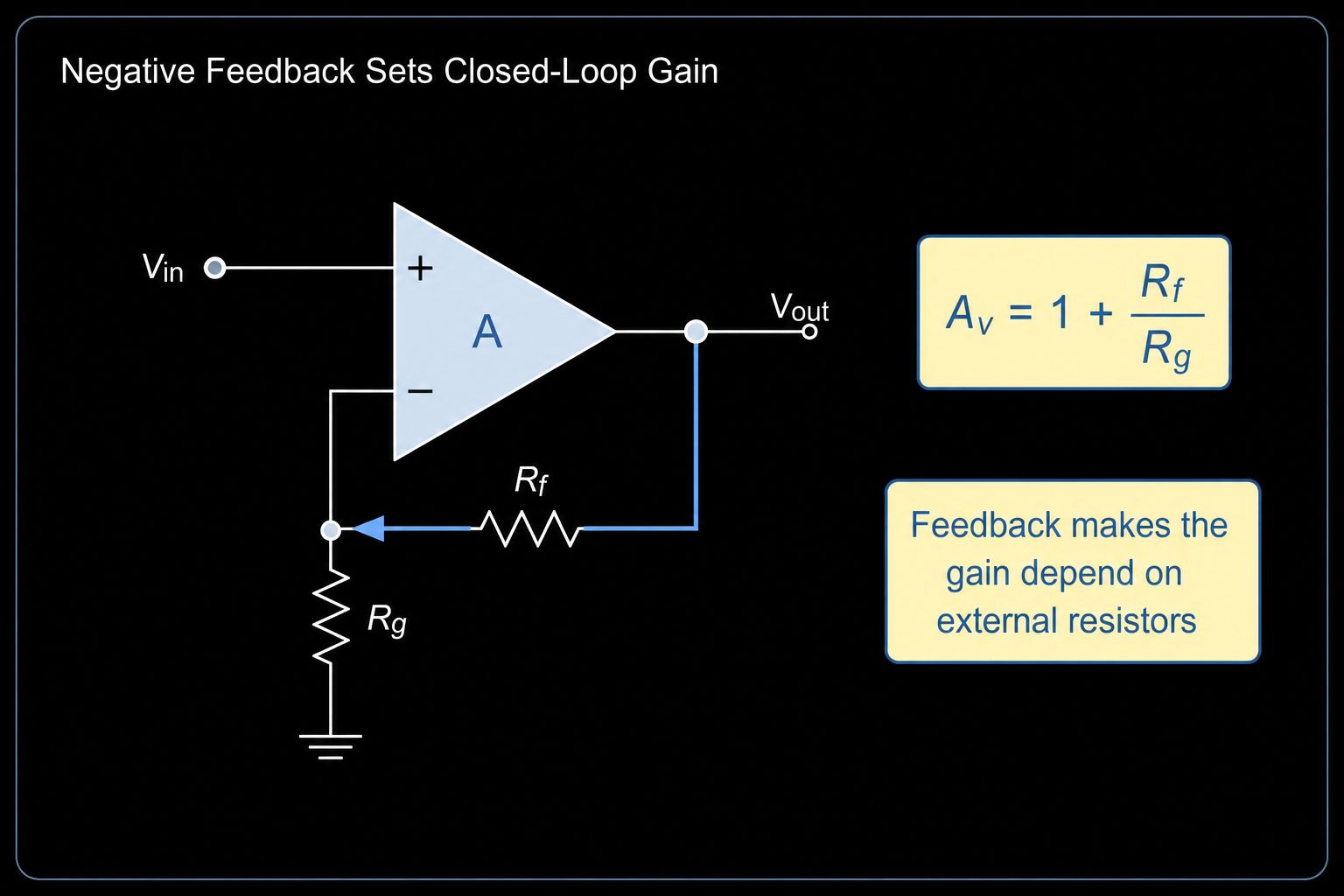
| Why feedback matters | Negative feedback sets the closed-loop gain and makes the circuit predictable | Feedback resistor values, stability, gain bandwidth and phase margin |
| Common circuit types | Voltage follower, non-inverting amplifier, inverting amplifier, summing amplifier, differential amplifier, active filter, integrator and differentiator | Required accuracy, frequency range, noise, load and package |
| Ideal vs real behavior | Ideal assumptions help explain formulas; real ICs have limits | Offset, bias current, slew rate, common-mode range, output current and thermal limits |
| Buying decision | The same circuit may need different op amps in audio, sensor, industrial or low-power designs | Exact part number, suffix, package, manufacturer, lifecycle and alternatives |
What Is an Operational Amplifier?
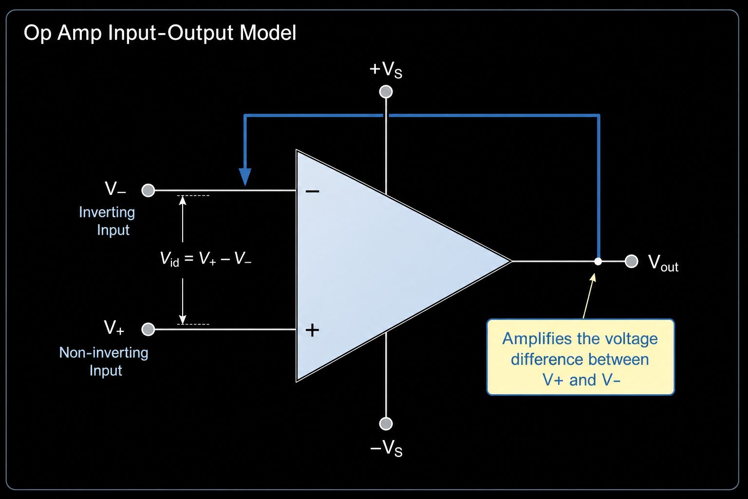
An operational amplifier is a high-gain differential amplifier integrated into a chip. It has a non-inverting input marked +, an inverting input marked -, and an output. When used without feedback, the very high open-loop gain can drive the output toward a supply rail from a small input difference. That behavior is useful for understanding the device, but most linear op amp circuits use negative feedback so the external network controls the closed-loop gain.
For a broader device-level introduction, see what is an operational amplifier. For selection, the important point is simple: the op amp is not the whole amplifier. The final behavior comes from the IC plus the resistor network, capacitor network, supply rails, input source and load. A part that works as a low-frequency buffer may fail in a high-gain sensor circuit or an audio stage if bandwidth, noise or input range is wrong.
Ideal Op Amp Rules and Real IC Limits
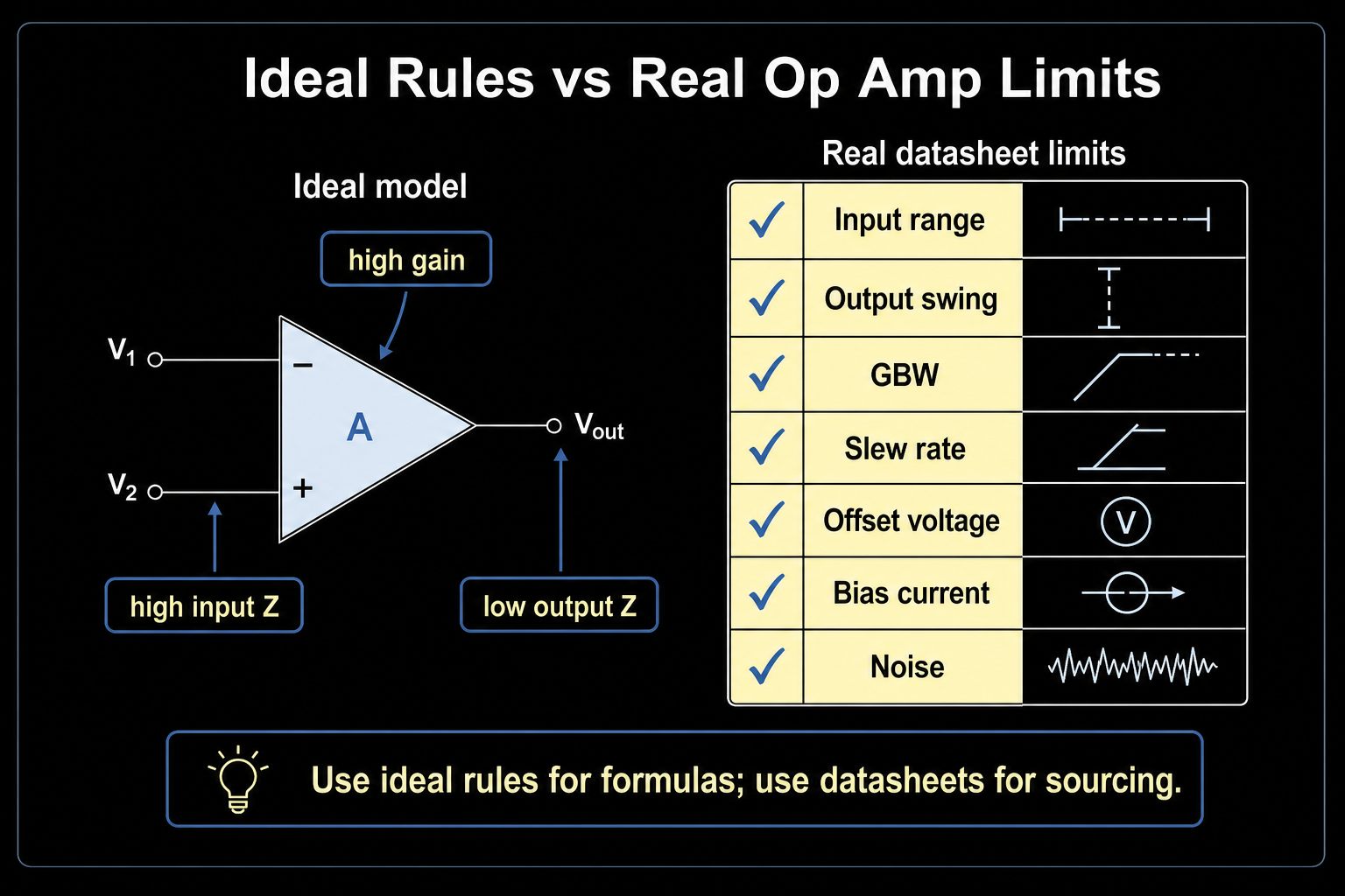
Many tutorials summarize the ideal op amp with very high gain, very high input impedance, very low output impedance and no offset. Those rules are useful for first-pass circuit analysis. They are not safe purchasing rules.
| Ideal assumption | Real datasheet limit | Procurement meaning |
|---|---|---|
| Infinite open-loop gain | Open-loop gain varies by device, load and temperature | Do not compare op amps only by basic function; check DC accuracy requirements |
| Infinite input impedance | Bipolar, JFET and CMOS inputs have different bias current | High-impedance sensors need low bias-current parts |
| Zero input offset | Every real op amp has input offset voltage and drift | Precision DC measurements need low-offset or zero-drift op amps |
| Unlimited bandwidth | Closed-loop bandwidth falls as gain increases | Gain and signal frequency must be checked together |
| Unlimited output swing | Output swing depends on rails and load current | Rail-to-rail wording still needs datasheet verification under load |
| Instant output change | Slew rate limits large-signal response | Audio, pulse and fast sensor signals may need higher slew rate |
Main Types of Op Amp Circuits
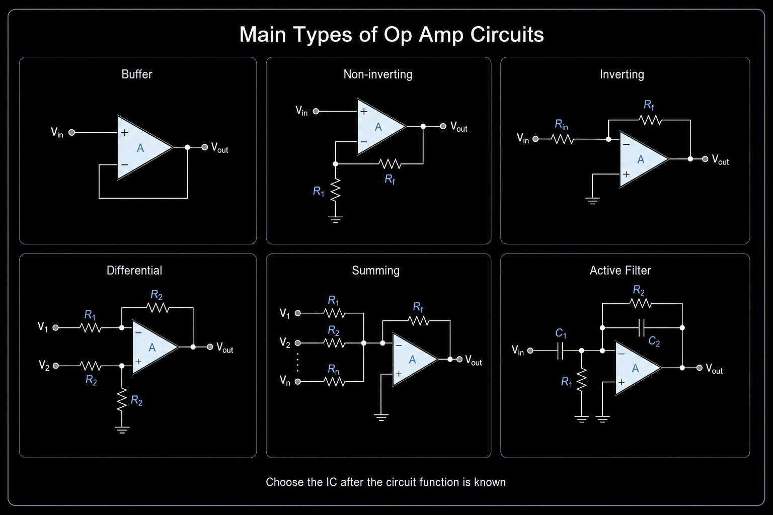
Voltage Follower / Buffer
A voltage follower connects the output back to the inverting input and feeds the signal into the non-inverting input. The voltage gain is approximately one, but the circuit provides high input impedance and lower output impedance. It is common in sensor interfaces, ADC drivers at modest speed, reference buffers and signal isolation stages.
Before sourcing, check unity-gain stability, input common-mode range, output swing, output current and capacitive-load behavior.
Non-Inverting Amplifier
A non-inverting amplifier keeps the input signal polarity and uses a resistor divider in the feedback path to set gain. Its common formula is Av = 1 + Rf/Rg. It is useful when the signal source should not be heavily loaded.
Selection checks include gain bandwidth product, input range, offset error, resistor tolerance, noise and whether the output can reach the required voltage range on the available supply.
Inverting Amplifier
For a deeper circuit walkthrough, use the inverting operational amplifier guide. An inverting amplifier applies the signal through an input resistor to the inverting node, while the non-inverting input is normally biased at a reference point. Its common formula is Av = -Rf/Rin. The circuit is useful for gain, signal inversion, summing and active filters.
Before replacing an op amp in this circuit, verify input bias current, feedback resistor values, bandwidth at the selected gain, output swing and stability with any capacitor in the feedback path.
Differential Amplifier and Instrumentation Amplifier
A differential amplifier responds to the difference between two signals and rejects common-mode voltage. A basic op amp differential stage depends strongly on resistor matching. For sensor bridges, current shunts, and industrial measurement, an instrumentation amplifier is often a better fit because it offers stronger common-mode rejection and easier gain setting.
Selection depends on common-mode range, CMRR, offset, gain accuracy, supply voltage and input protection requirements.
Summing, Integrator and Differentiator Circuits
A summing amplifier combines multiple input signals through resistors. For time-domain circuit examples, see the Op Amp Integrator and Op Amp Differentiator guides. An integrator uses a capacitor in the feedback path to accumulate input over time. A differentiator responds to the rate of input change. These circuits are valuable, but they can expose stability, noise, and bandwidth limits quickly.
For production, check whether the circuit uses a practical compensation network, whether the op amp is stable at the intended gain, and whether input noise or high-frequency gain creates false output movement.
Comparator-Like Use
An op amp can be used in comparator-like operation, but a dedicated comparator is often the safer choice for threshold detection, fast switching, logic-level output, and recovery from saturation. Use an op amp this way only after confirming input common-mode range, output recovery time, output logic compatibility, and the device manufacturer's guidance. For more detail, see the Op Amp Comparator guide.
How to Choose an Operational Amplifier
| Selection factor | Why it matters | What to check |
|---|---|---|
| Supply voltage | A dual-supply op amp may not work correctly on a single low-voltage rail | Operating supply range, single/dual-supply support, rail-to-rail requirements |
| Input common-mode range | Inputs outside the allowed range can distort or saturate the output | Minimum and maximum input voltage over temperature |
| Output swing and load | Output may not reach the rails, especially under load | Output-high/output-low limits at the required load current |
| Gain bandwidth product | Closed-loop bandwidth shrinks as gain rises | Target gain, signal bandwidth, and stability margin |
| Slew rate | Large fast signals need enough output transition speed | Maximum signal amplitude and frequency |
| Input offset and drift | DC error can dominate precision sensor circuits | Offset voltage, drift, and required DC accuracy |
| Input bias current | Bias current creates error with high source resistance | Source impedance and input technology such as bipolar, JFET, or CMOS |
| Noise and distortion | Low-level sensor and audio circuits need stronger noise checks | Voltage noise, current noise, distortion, and frequency range |
| Package and channels | Single, dual and quad versions affect PCB layout and BOM count | Channel count, package, pinout, and assembly format |
| Lifecycle and source | Legacy or heavily multi-sourced parts need controlled sourcing | Manufacturer, exact suffix, lifecycle, approved alternatives, and traceability |
Popular Operational Amplifier ICs to Check
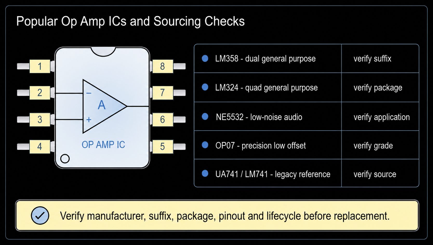
For general product discovery, start from operational amplifier ICs. The part numbers below are widely used reference points across general-purpose, audio, precision, and high-input-impedance designs. Exact electrical limits can vary by manufacturer and suffix, so verify the selected datasheet, package, temperature grade, and lifecycle before approving a part or substitute.
| Part number | Common positioning | Typical use | Sourcing caution |
|---|---|---|---|
| LM358 | Dual general-purpose op amp | Low-frequency signal conditioning, buffering, control, and general analog circuits | Check suffix, package, supply range, input range, output swing, and manufacturer source |
| LM324 | Quad general-purpose op amp | Multi-channel analog signal conditioning and control circuits | Check package, pinout, output swing, and differences between manufacturers |
| NE5532 | Dual low-noise audio op amp | Audio preamplifiers, filters, and low-noise analog stages | Verify package, source authenticity, supply rails, noise, and audio-circuit requirements |
| OP07 | Precision low-offset op amp | Precision DC measurement, instrumentation, and low-offset signal conditioning | Verify offset grade, package, supply requirements, and manufacturer-specific limits |
| UA741 / LM741 | Legacy general-purpose op amp | Legacy maintenance, replacement analysis, and educational circuits | Do not assume modern low-voltage or rail-to-rail behavior; validate any alternative in the actual circuit |
| TL071 / TL072 / TL082 | JFET-input op amp family | High-input-impedance analog stages, audio, and active filters | Check noise, slew rate, supply rails, package, and manufacturer source |
Common Mistakes
- Treating the ideal op amp as a real datasheet. Ideal rules help with formulas, but they do not confirm input range, output swing, offset, slew rate, noise or stability.
- Choosing only by part number popularity. LM358, LM324, NE5532 and UA741 are searched often, but each has different circuit limits and many suffix/package variants.
- Ignoring the power rails. A circuit diagram may show an ideal op amp, while the real board has a single 3.3 V, 5 V, 12 V or dual supply rail.
- Using an op amp as a comparator without checking recovery and output behavior. For fast threshold detection, a comparator may be the correct component.
- Calling an alternative a drop-in replacement before checking pinout, package, supply range, offset, bandwidth, load, temperature grade and lifecycle.
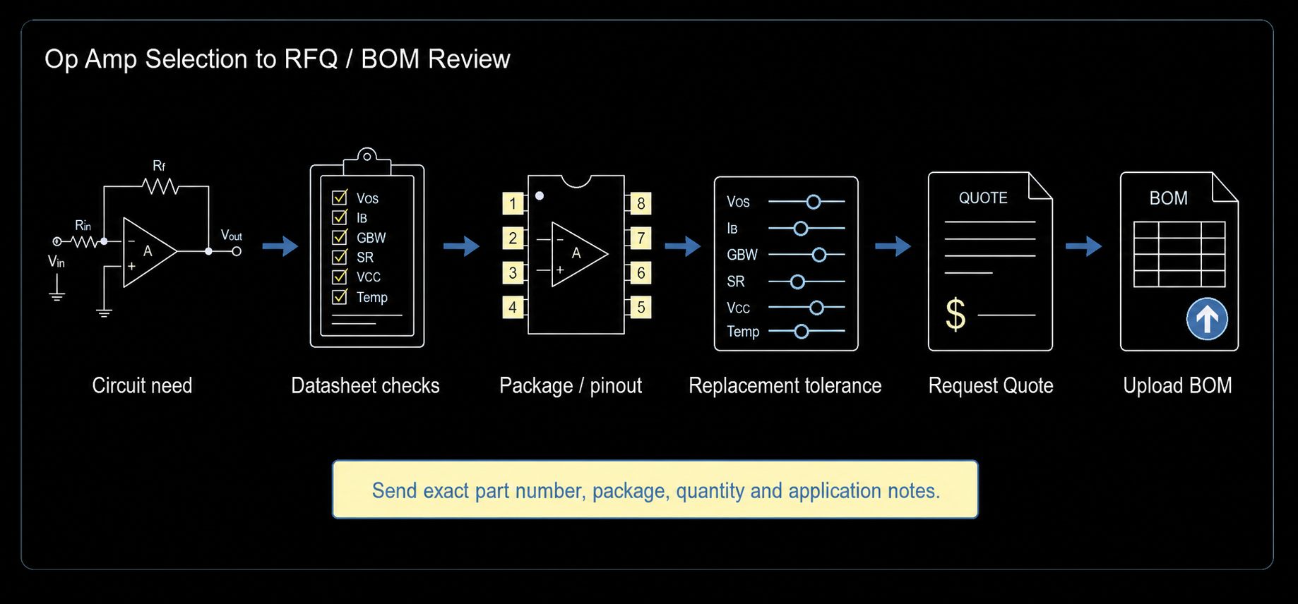
Replacement and BOM Review Checklist
| Check | Why it matters | What to send for RFQ/BOM review |
|---|---|---|
| Exact part number and suffix | Suffix may define package, grade, reel/tube and temperature options | Full marking or ordering code |
| Manufacturer | Multi-source families may not be identical in every limit | Preferred brand or accepted brands |
| Package and pinout | Prevents PCB mismatch and assembly issues | DIP, SOIC, TSSOP, SOT-23, MSOP and pin count |
| Supply voltage | Confirms single/dual-supply compatibility | Board rail values and tolerance |
| Circuit function | Defines bandwidth, offset, noise and output current needs | Buffer, inverting, non-inverting, audio, sensor, filter, comparator-like use |
| Quantity and schedule | Affects quote validity and sourcing route | Required quantity, target delivery date and region |
| Replacement tolerance | Determines whether parametric alternatives are acceptable | Drop-in only, same footprint preferred, or redesign allowed |
Related Op Amp Guides
- What Is an Operational Amplifier? for a fundamentals-first explanation of op amp operation.
- Operational Amplifier Building Blocks for a circuit-by-circuit overview.
- Non-Inverting Operational Amplifier and Inverting Operational Amplifier for the two most common closed-loop gain configurations.
- Summing Amplifier, Differential Amplifier, and Instrumentation Amplifier for multi-input and precision measurement circuits.
- Op Amp Comparator, Op Amp Integrator, and Op Amp Differentiator for threshold and time-domain functions.
FAQ
What is the short summary of an operational amplifier?
An operational amplifier is a high-gain analog IC that amplifies the voltage difference between its two inputs. In practical circuits, negative feedback and external components set the usable gain and function.
What is the difference between an op amp and an operational amplifier?
There is no practical difference. Op amp is the common short form of operational amplifier. The terms refer to the same type of analog amplifier IC.
Which op amp circuit should I learn first?
Start with the voltage follower, non-inverting amplifier and inverting amplifier. These three circuits explain feedback, gain, input impedance and output behavior used in many other op amp applications.
How do I choose an op amp for a BOM?
Start from the circuit function, supply rails, signal frequency, gain, accuracy, load and package. Then verify the exact manufacturer datasheet before approving a part number or substitute.
Can LM358 replace LM324?
Not directly in most PCB designs because LM358 is commonly a dual op amp while LM324 is commonly a quad op amp, so package and pinout usually differ. They may be related general-purpose families, but replacement must be checked at the schematic and PCB level.
Is a 741 op amp still a good choice?
UA741 / LM741 is useful for learning and some legacy replacement work, but it is not automatically suitable for modern low-voltage, rail-to-rail, low-power or precision designs. Check the real requirements before using it in a new BOM.
Request Quote or Upload BOM
If you need operational amplifier ICs for production, send the exact part number, package, quantity and application notes. ApexComponent can help review common op amp families such as LM358, LM324, NE5532, OP07, UA741 / LM741 and TL07x / TL08x, then confirm sourcing options or alternatives based on datasheet, package and BOM requirements.
Send Inquiry for a direct quote request, or Upload BOM when multiple analog ICs need package and replacement review.