
A pull-up resistor connects a digital signal to a positive supply so the signal defaults to HIGH when no device drives it LOW. Its resistance must be low enough to meet logic and timing limits, yet high enough to keep current within the driver’s capability. A pull-down resistor provides the opposite default: LOW.
A microcontroller button input and an I²C bus can both need pull-ups, but they have different selection limits. This guide explains the wiring, compares internal and external bias, and works through resistor-value calculations before you put the part on a production BOM.
What does a pull-up resistor actually do?
A pull-up establishes a default voltage on a node that would otherwise be undriven. The input reads that voltage; the resistor does not command the firmware to return a particular value. Check the pin’s electrical mode and logic thresholds as well as the resistor connection.
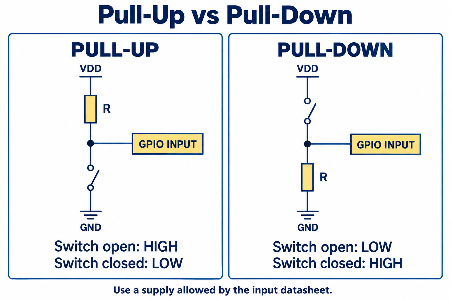
With a switch open, the node sits close to the pull-up supply, subject to leakage. Closing a switch to ground creates a current path through the resistor and moves the node toward LOW. The resistor limits current in that path. Wiring the same switch directly between the supply and ground would bypass that protection.
A pull-up is a circuit role, not a special resistor technology. An ordinary fixed resistor can serve as a pull-up or pull-down depending on its connection. Package, tolerance, working voltage, and power rating still belong in the part specification.
Floating CMOS inputs and slow transitions can increase supply current or cause unstable behavior. The practical check is to keep an input inside valid voltage and transition limits, as discussed in TI’s guidance on slow or floating CMOS inputs. A larger resistor saves current when the node is held LOW, but also gives leakage and coupled interference more influence over its voltage.
Pull-up vs pull-down resistor: which wiring should you use?
Choose the direction from the required idle state. Use a pull-up for an idle HIGH input with a switch to ground. Use a pull-down for an idle LOW input with a switch to the valid input supply. The active state then reverses, so firmware must use the matching polarity.
| Check | Pull-up resistor | Pull-down resistor |
|---|---|---|
| Resistor connection | Signal node to positive logic supply | Signal node to ground |
| Switch connection | Signal node to ground | Signal node to positive logic supply |
| Switch open | HIGH | LOW |
| Switch closed | LOW; active-low input | HIGH; active-high input |
| Main verification | HIGH threshold and LOW-state current | LOW threshold and HIGH-state current |
These states agree with Arduino’s digital pin mode documentation. They assume a functioning switch, common ground, and a supply permitted by the input datasheet.
How do you choose a pull-up resistor value for a GPIO input?
Check both ends of the allowable resistance range. A resistor that is too small increases current while the node is LOW. A resistor that is too large can leave too little HIGH-state margin once input leakage, other connected components, and required response time are included.
- Collect the actual limits. Record the supply range, guaranteed HIGH and LOW thresholds, worst-case leakage, pin mode, temperature range, and the current permitted in the LOW state.
- Check the idle voltage. For a simplified pull-up with leakage toward ground, require Vnode = VPU − Ileak,totalR to stay above VIH,min. Include all leakage paths, not only the MCU pin.
- Check the active-state current. With an ideal closed switch to ground, I = VPU/R and resistor dissipation P = VPU2/R. With a semiconductor driver, use its specified LOW voltage and sink capability.
- Check tolerance and timing. Use the smallest possible resistance for the current check and the largest for leakage and RC checks. Validate noise margin and input transition requirements on the assembled circuit.
Simplified pull-down leakage bound: R ≤ VIL,max / Ileak,total,max
For the first bound, VIH,min means the guaranteed HIGH threshold required at the supply and temperature corner being checked. For the second, use leakage that sources current into the node and the corresponding guaranteed LOW threshold. These equations describe static leakage only; they do not establish acceptable noise immunity or switching speed.
Illustrative GPIO calculation: assume a fixed 3.3 V supply, a required HIGH threshold of 2.31 V, and total leakage of 1 µA toward ground. A 10 kΩ pull-up loses 0.010 V to leakage, so its predicted idle voltage is 3.29 V. When an ideal switch closes, current is 0.33 mA and dissipation is 1.089 mW. These are assumed design inputs, not specifications for a named microcontroller.
| Resistance | LOW-state current | Resistor dissipation | What to review |
|---|---|---|---|
| 4.7 kΩ | 0.702 mA | 2.32 mW | Higher current; smaller voltage shift for a given leakage current |
| 10 kΩ | 0.330 mA | 1.089 mW | Check the actual thresholds, response time, and noise environment |
| 47 kΩ | 0.0702 mA | 0.232 mW | Greater sensitivity to leakage and node capacitance |
| 100 kΩ | 0.0330 mA | 0.109 mW | Lower active-state current; verify idle-state margin carefully |
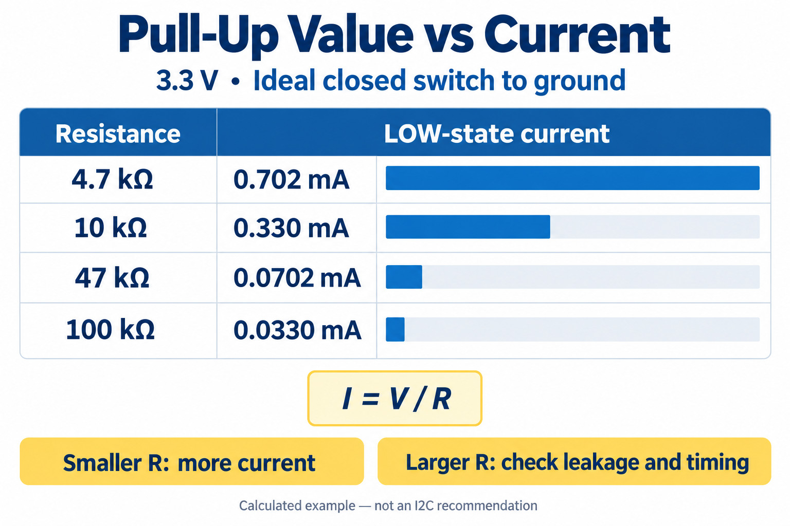
A held button can keep drawing bias current throughout its active time. For a battery-powered design, multiply that current by the expected active duty cycle rather than assuming the resistor consumes the same power in both switch states.
Can you use the microcontroller’s internal pull-up?
Use an internal pull-up when its guaranteed strength and enabled states satisfy the input requirement. An external resistor is useful when you need a controlled value, a bias during a state where the internal pull is unavailable, or a resistance chosen for a specific interface load.
Arduino’s UNO Rev3 documentation lists 20–50 kΩ internal pull-ups on its ATmega328-based digital pins. That range belongs to that documented board family; it is not a universal specification for every Arduino or MCU. Do not model a wide internal range as an exact 10 kΩ component.
Configuration also matters. Microchip’s GPIO overview describes input and output modes and the role of pull-up and pull-down bias. Confirm that your selected pin is configured as a digital input, then check the corresponding registers in your own device documentation.
| Requirement | Internal pull-up review | External resistor review |
|---|---|---|
| Simple local button | Confirm input mode, pull enable, and valid logic margins | Specify a value if the internal limits do not meet the requirement |
| Defined state during reset or sleep | Read the pin’s documented reset and low-power behavior | Check whether the bias supply remains present in those states |
| Open-drain bus | Prove that the full pull-strength range meets current and rise-time limits | Choose the resistance from the interface’s electrical limits |
| Cable or exposed connector | Evaluate leakage, capacitance, and interference at the input | Evaluate the complete input network, including protection or filtering |
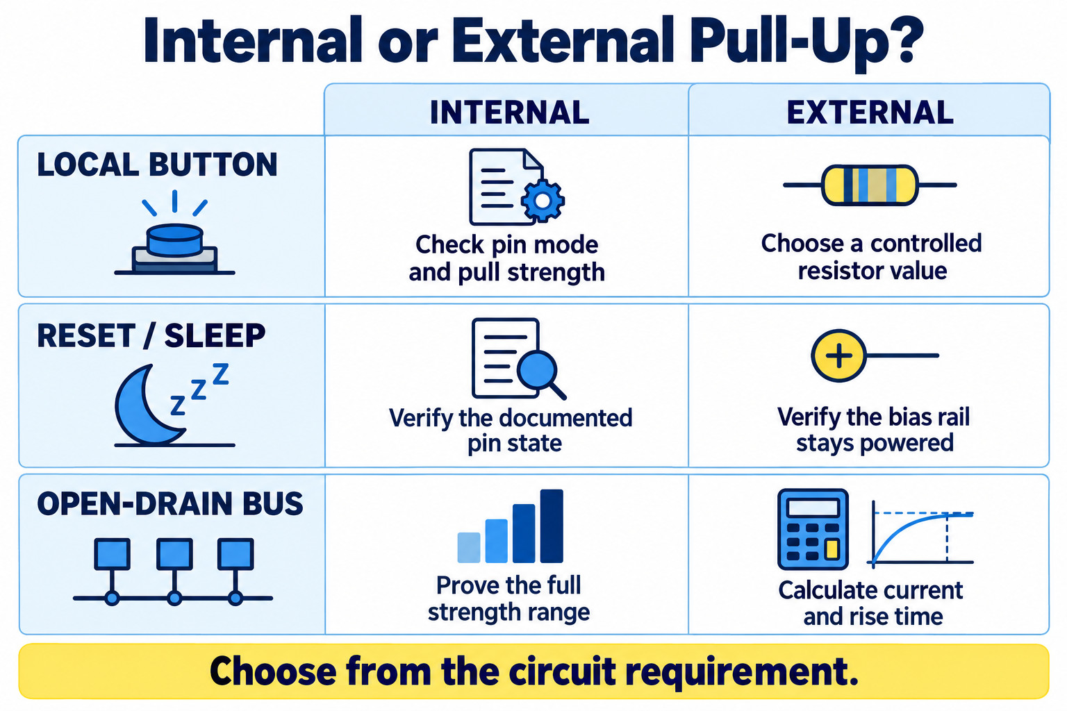
An external resistor connected to an unpowered rail is not automatically a valid bias source. Review power sequencing and permitted pin voltages. For broader device requirements, see our microcontroller selection guide.
How do you calculate an I²C pull-up resistor?
For a passive I²C pull-up, the driver’s sink capability sets a minimum resistance and the bus rise-time limit sets a maximum. Calculate the range for each line, include every installed pull-up, and choose a value that stays within it at the relevant component and supply corners.
TI application report SLVA689 gives the following bounds for the passive RC model. The rise-time factor 0.8473 describes the 30%–70% transition of an exponential RC edge.
Rmax = tr,max / (0.8473 × Cbus,max)
Predicted 30%–70% rise time: tr = 0.8473 × Reffective × Cbus
Use a guaranteed sink current IOL at the allowed LOW voltage VOL,max for the weakest connected driver. Cbus includes the connected devices, wiring, and measurement loading. The model needs review if buffers, active rise-time accelerators, or other non-passive circuitry are present.
NXP’s UM10204 specification, Rev. 7.0, Table 11 gives a maximum rise time of 300 ns for Fast-mode I²C, which supports clock frequencies up to 400 kHz. Clock rate alone does not tell you the required resistance: capacitance changes the upper bound.
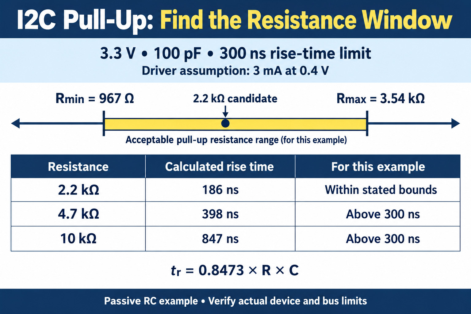
This calculated Fast-mode I²C example assumes a fixed 3.3 V pull-up supply, 100 pF capacitance per line, a 300 ns maximum rise time, and a driver guaranteed to sink 3 mA at 0.4 V. The passive model gives a minimum resistance of 967 Ω and a maximum of 3.54 kΩ. A 2.2 kΩ resistor predicts a 186 ns rise time, while 4.7 kΩ predicts 398 ns and exceeds the stated timing limit. At ±5% tolerance, the 2.2 kΩ component ranges from 2.09 to 2.31 kΩ, still inside those fixed bounds. These results make 2.2 kΩ a candidate for verification, not a universal I²C value. Replace the assumptions with your actual supply limits, weakest driver capability, installed capacitance, and temperature conditions. Count parallel pull-ups on every module and verify both SDA and SCL on the assembled bus. This is not a measured board.
| Resistance | Predicted rise time | Result for the stated bounds |
|---|---|---|
| 2.2 kΩ | 186 ns | Within both nominal bounds; a candidate for verification |
| 4.7 kΩ | 398 ns | Exceeds the 300 ns limit in this example |
| 10 kΩ | 847 ns | Exceeds the 300 ns limit in this example |
Multiple pull-ups combine in parallel. Two 4.7 kΩ resistors on the same line and supply produce 2.35 kΩ effective resistance; four produce 1.175 kΩ. Count pull-ups on modules and daughterboards before adding another one. Check both SDA and SCL, then verify their LOW levels and rising edges on the completed system. See also I²C vs SPI EEPROM selection.
Why does an input still fail after adding a pull-up?
Measure the failing state before changing the resistor. An unexpected reading can come from incorrect pin configuration, a wrong supply, slow edges, switch bounce, or an extra load. A single DC measurement cannot show all of those faults.
| Symptom | First check | Next action |
|---|---|---|
| Released button reads randomly | Voltage at the pin; resistor connection; input and pull-enable registers | Verify the default voltage against the input thresholds |
| One press creates several events | Waveform during the press and release | If contacts bounce, add an appropriate debounce method |
| I²C fails after another module is added | Effective resistance, total load, LOW voltage, and rise time | Recalculate the bounds for the assembled bus |
| Input is correct only after startup | Pin voltage and configuration throughout reset | Provide the documented startup bias requirement |
| Battery drain rises while a switch is held | Current through the active pull-up path | Include active duration and leakage in the power budget |
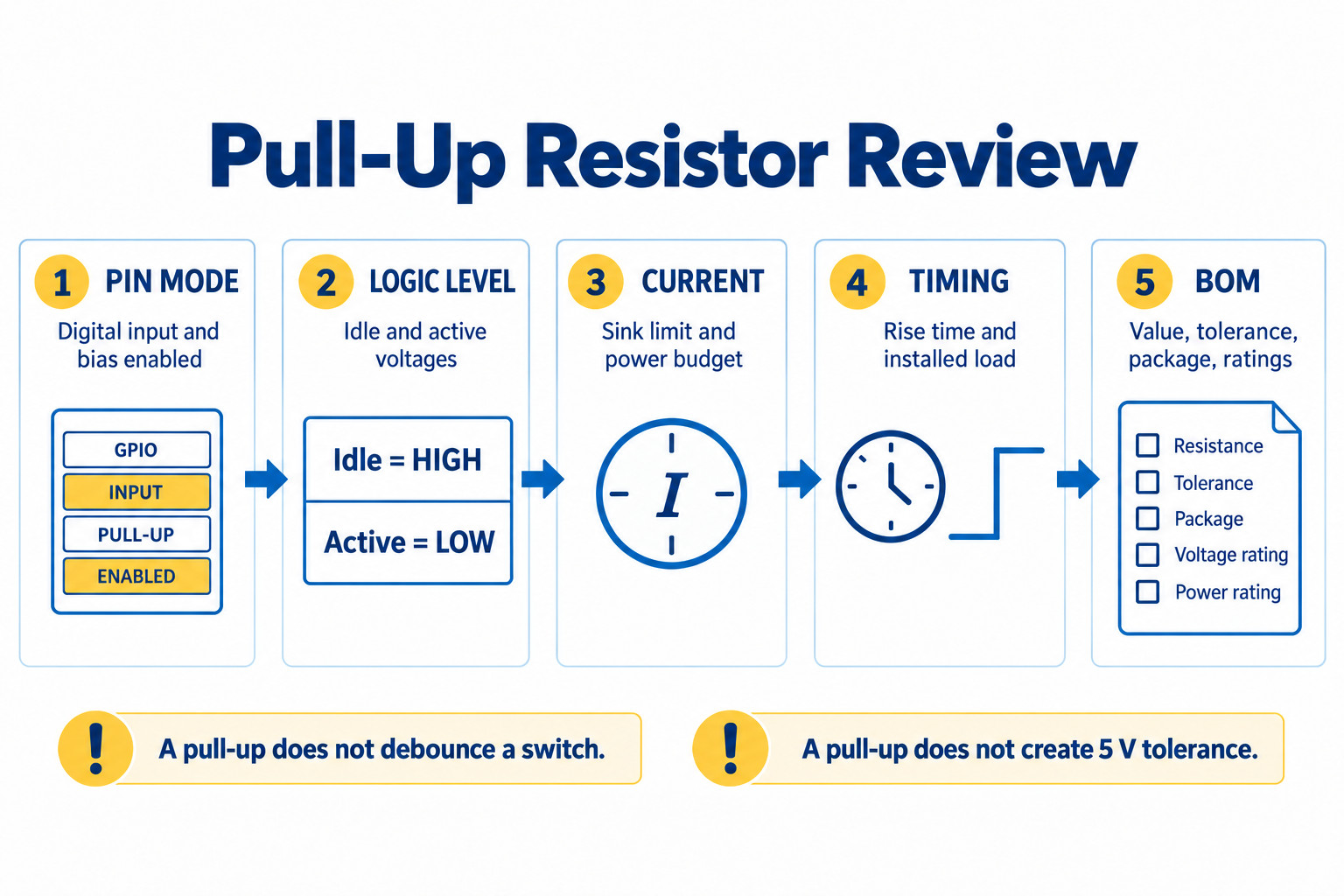
Two frequent mistakes deserve a separate check. A pull-up does not debounce a mechanical switch. It also does not make a 3.3 V input automatically tolerant of a 5 V pull-up supply. Check the input’s permitted operating voltage and powered-off conditions before choosing that rail.
What should a pull-up resistor BOM entry include?
Specify the physical component and its permitted substitution limits. “10 kΩ pull-up” describes a function and a nominal value, but it does not identify an orderable part or prove that another package or tolerance is acceptable.
- Resistance and tolerance: approved nominal value and permitted minimum/maximum, including any temperature drift relevant to the calculated margin.
- Package: footprint and mounting type; identify the size convention explicitly, such as 0603 imperial / 1608 metric.
- Electrical ratings: rated power, working voltage, and any manufacturer derating needed for the operating temperature.
- Part identity: manufacturer part number, reference designator, quantity, and approved alternatives.
- Circuit conditions: bias supply and startup behavior; for I²C, mode, estimated capacitance, and effective installed pull-up resistance.
If a replacement changes tolerance or package, rerun the relevant bounds and footprint checks. A part with the same nominal resistance can still fall outside the approved electrical or assembly requirement. This is where a resistor selection note helps purchasing preserve the design intent.
Prepare the resistance, tolerance, package, and approved part numbers before requesting sourcing help. Include the MCU or interface IC in a multi-part inquiry so the electrical assumptions are clear.
Browse ResistorsUpload BOM / Request QuotePull-up resistor FAQ
Is 10 kΩ always the right pull-up resistor value?
No. Check the input thresholds, leakage, current budget, and timing. A 10 kΩ resistor produces a calculated 847 ns rise time at 100 pF in the passive RC example above, exceeding its 300 ns limit.
Can the same resistor be a pull-up or a pull-down?
Yes. The connection determines the role: signal to a positive logic supply for a pull-up, or signal to ground for a pull-down. Its value and physical ratings must suit the resulting circuit.
Does a smaller pull-up resistor mean a stronger pull-up?
Yes, for the same supply: a smaller resistance can deliver more current. It reduces the voltage shift caused by a given leakage current, while increasing LOW-state current. Check that the driver can still achieve a valid LOW.
Do all microcontrollers have internal pull-down resistors?
No universal pin feature should be assumed. Read the exact device’s pin configuration and electrical tables for pull-up and pull-down availability, strength, reset state, and low-power behavior.
Can I replace I²C pull-ups with the MCU’s internal pull-ups?
Only if their full guaranteed range meets the bus’s electrical and timing limits in every required state. Calculate effective resistance and rise time, including connected modules, then verify the assembled interface.
Technical sources and calculation method
This guide uses manufacturer and platform documentation for electrical principles. Numerical tables are original calculations using the stated assumptions and rounded results. They are not laboratory measurements or a qualification of a specific board.
- Texas Instruments, SCBA004E: Implications of Slow or Floating CMOS Inputs — input behavior and transition requirements.
- Texas Instruments, SLVA689: I2C Bus Pull-Up Resistor Calculation — passive pull-up bounds and RC model.
- NXP, UM10204 Rev. 7.0: I2C-bus specification and user manual — bus modes and Table 11 timing limits.
- Arduino: INPUT, INPUT_PULLUP, and OUTPUT — input mode and button polarity.
- Arduino UNO Rev3 with Long Pins — board-specific internal pull-up range.
- Microchip: GPIO and Software-Based Delays — digital input and weak pull-up configuration.