
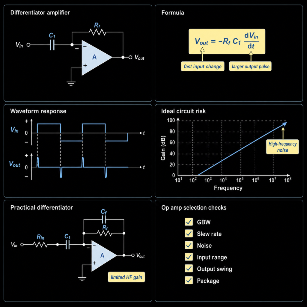
An op amp differentiator amplifier is a circuit that gives an output based on how fast the input voltage is changing. If the input changes quickly, the output becomes larger. If the input is steady, the ideal output is zero. This is why the circuit is useful for edge detection, pulse shaping, control signals, and waveform study.
For the ideal inverting differentiator, assuming the op amp remains in its linear operating range, the basic relationship is:
Vout = -Rf x C1 x dVin/dt
The minus sign means the output is inverted. A rising input edge gives a negative output pulse. A falling input edge gives a positive output pulse.
This article explains the circuit in simple English. It also adds practical checks for real op amp IC selection. A real differentiator is not only a formula. The chosen op amp must have enough bandwidth, enough slew rate, suitable input and output range, low enough noise, and the right package for the board.
If you already have a part number, supply voltage, signal frequency, package, and quantity, you can review available operational amplifier ICs or send the BOM for sourcing support.
Quick Answer
| Question | Short Answer |
|---|---|
| What does a differentiator amplifier do? | It creates an output related to the rate of change of the input voltage. |
| What is the main formula? | Vout = -Rf x C1 x dVin/dt for the ideal inverting op amp differentiator. |
| What happens with a DC input? | The ideal output is zero because a steady voltage has no change with time. |
| What happens with a square wave input? | The output becomes short pulses at the rising and falling edges. |
| Why is the simple circuit risky? | It can increase high-frequency noise and may become unstable at high frequency. |
| What should buyers check? | GBW, slew rate, noise, input/output range, offset, bias current, package, pinout, lifecycle, and real stock status. |
What Is a Differentiator Amplifier?
A differentiator amplifier is an op amp circuit that works like a small analog math block. It responds to change.
In many amplifier circuits, the output is based mainly on input size. In a differentiator, the output is based mainly on input speed. A slow input change gives a smaller output. A fast input change gives a larger output.
This makes the differentiator different from a normal inverting amplifier. In a normal inverting amplifier, a resistor brings the input signal into the inverting input. In a basic op amp differentiator, a capacitor is placed at the input instead. The feedback part uses a resistor.
The capacitor is important because its current depends on how quickly the input voltage changes. For an ideal steady DC input, the capacitor current becomes zero after the transient settles, so the ideal differentiator output also becomes zero.
Basic Op Amp Differentiator Circuit
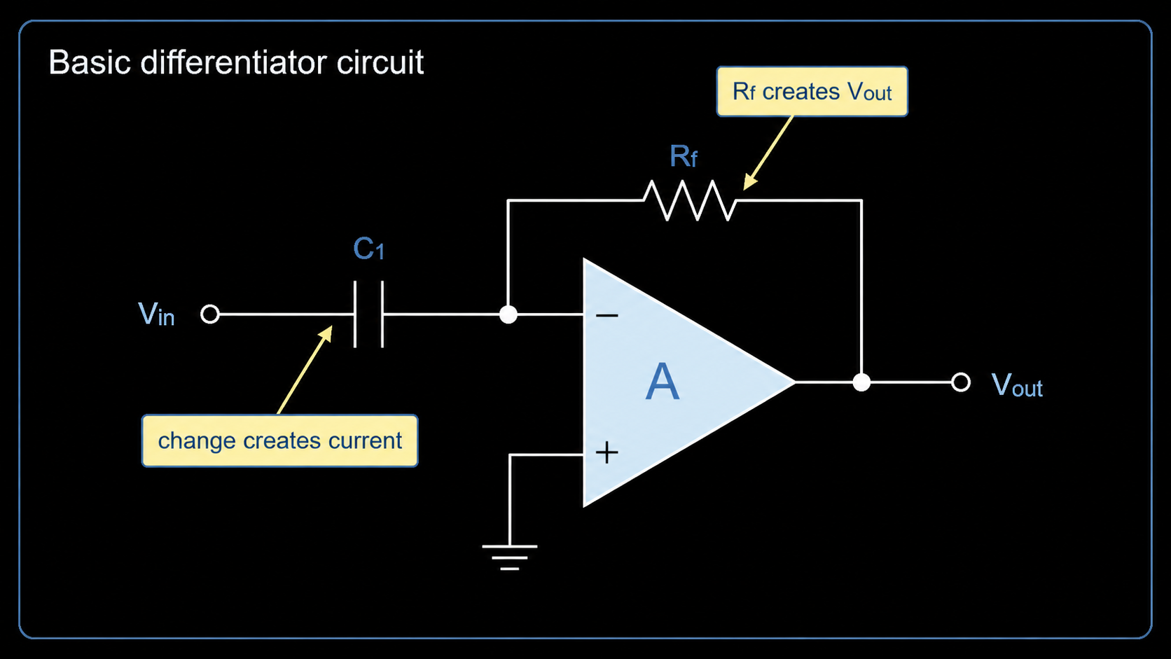
A basic inverting differentiator uses these parts:
| Circuit Part | Role |
|---|---|
Vin | The input signal. |
C1 | The input capacitor. It turns voltage change into current. |
Rf | The feedback resistor. It turns that current into output voltage. |
| Op amp | Holds the inverting input near the reference point and drives the output. |
Vout | The output signal, inverted from the input change. |
In simple words, the capacitor creates a current when the input voltage changes. A faster voltage change creates a larger capacitor current. That current flows through the feedback resistor. The resistor changes the current into an output voltage.
The op amp uses negative feedback to keep the inverting input close to the non-inverting input voltage. For many basic examples, the non-inverting input is tied to ground or to a mid-supply reference. This makes the inverting input act like a "virtual ground" during normal linear operation.
For a deeper foundation on this idea, read the inverting operational amplifier guide.
Differentiator Amplifier Formula
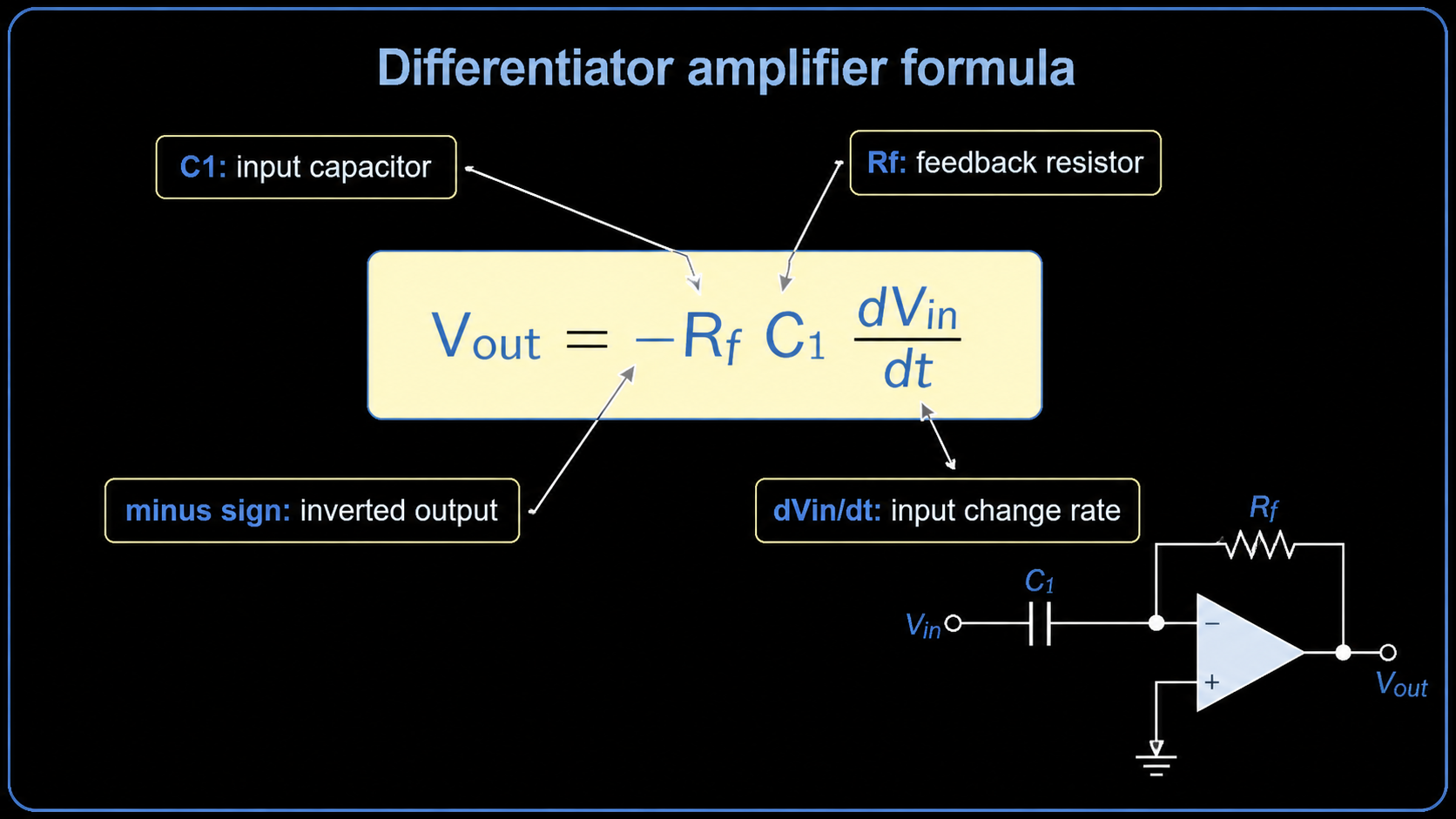
For the ideal inverting differentiator:
Vout = -Rf x C1 x dVin/dt
Here is what each part means:
| Term | Meaning |
|---|---|
Vout | Output voltage. |
Rf | Feedback resistor value. |
C1 | Input capacitor value. |
dVin/dt | How fast the input voltage changes with time. |
- sign | The output is inverted because the signal goes into the inverting input. |
You do not need advanced math to understand the main idea. The term dVin/dt means "change in input voltage divided by change in time."
Example:
Input changes by 1 V in 1 ms  -> slower change
Input changes by 1 V in 1 us  -> much faster change
The second case gives a much larger output because the input changes in a much shorter time.
What the Waveforms Mean
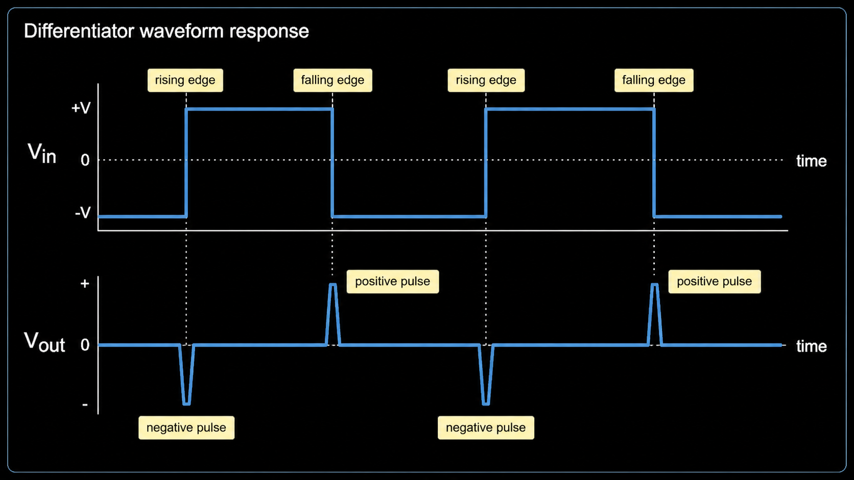
The differentiator is easier to understand if you look at waveforms.
| Input Signal | Ideal Output Behavior |
|---|---|
| DC voltage | Zero output, because the input is not changing. |
| Slow ramp | A small steady output while the ramp is rising or falling. |
| Fast ramp | A larger steady output while the ramp is rising or falling. |
| Square wave | Short pulses at the rising and falling edges. |
| Sine wave | A shifted sine-like output whose size increases with frequency, within circuit limits. |
For a square wave, most of the change happens at the edges. The differentiator reacts strongly at those edges. That is why the output looks like narrow spikes or pulses.
This can be useful in edge detection and pulse shaping. But it also explains a risk: noise often contains fast high-frequency changes. A differentiator can increase that noise if the design is too ideal.
Why an Ideal Differentiator Is Not Enough
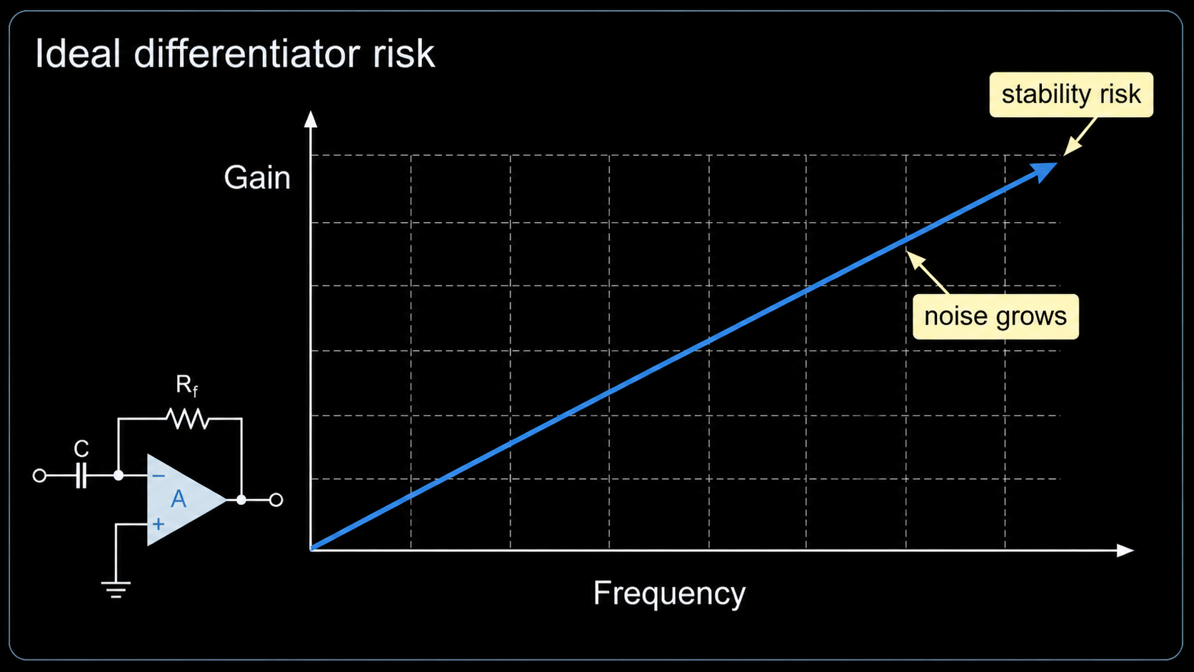
The simple circuit is useful for learning, but it is not always a good production circuit.
The main problem is high-frequency gain. In a basic differentiator, gain rises as frequency rises. At low frequency, the input capacitor has high reactance, so the output is small. At higher frequency, the capacitor reactance falls, so the output becomes larger.
That sounds useful until the frequency becomes too high. Real op amps have limited bandwidth and limited phase margin. The circuit may amplify noise, ring, or oscillate. It may also produce an output that is not useful for the real signal.
Texas Instruments' differentiator circuit resources note that a practical design works over a chosen frequency range, not over all frequencies. TI also states that the ideal differentiator needs added parts such as an input resistor, a feedback capacitor, or both, to make the circuit stable in real use.
Practical Op Amp Differentiator
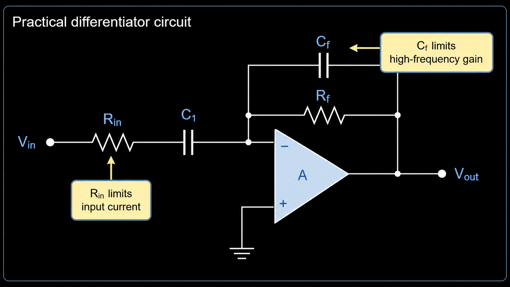
A practical differentiator keeps the useful response while limiting excessive high-frequency gain.
Common improvements include:
| Added Part | What It Does |
|---|---|
| Series input resistor | Limits high-frequency input current and stops the gain from rising forever. |
Small feedback capacitor across Rf | Reduces high-frequency gain and improves stability. |
| Bias/reference network | Sets the correct input reference for single-supply circuits. |
| Supply bypass capacitors | Helps the op amp stay stable and clean near the power pins. |
The goal is not to make the circuit respond to every possible frequency. The goal is to make it respond well inside the frequency range your system needs.
For example, TI's differentiator design example defines a frequency band, supply voltage, reference voltage, and output range. That is a practical way to think. First decide what signal range matters. Then choose component values and an op amp that can work inside that range.
How to Choose an Op Amp for a Differentiator Circuit
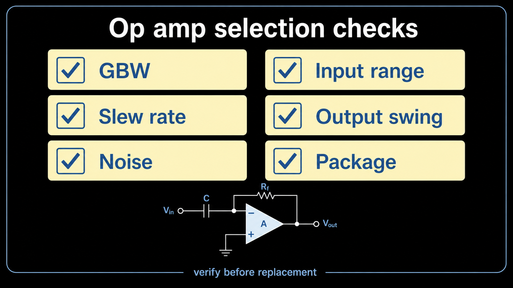
Do not choose the op amp only by price or package. A differentiator can stress an op amp in ways that a simple low-speed amplifier does not.
Use this checklist before approving a part.
| Check | Why It Matters |
|---|---|
| Gain bandwidth product | The op amp must support the closed-loop behavior in the needed frequency range. |
| Slew rate | Fast output pulses need enough output speed. Low slew rate can distort the waveform. |
| Input noise | Differentiators can increase high-frequency noise, so noise matters. |
| Input offset voltage | Offset can create errors, especially in low-level signal circuits. |
| Input bias current | Bias current can create voltage errors through resistors. |
| Input common-mode range | The input pins must stay inside the allowed voltage range. |
| Output swing | The output must reach the needed voltage without clipping. |
| Supply voltage | Check single-supply or dual-supply operation. |
| Stability with capacitors | The circuit contains capacitors, so stability must be reviewed. |
| Package and pinout | The part must fit the PCB footprint before it can be a real replacement. |
| Lifecycle | Check whether the exact orderable part is active, NRND, EOL, or obsolete. |
This is also a sourcing issue. Two op amps with the same package can behave very differently. Before replacing a part, check the datasheet, pinout, supply range, bandwidth, slew rate, input/output range, noise, package code, and lifecycle.
Common Mistakes
Mistake 1: Treating the Ideal Circuit as a Real Product Design
The ideal circuit is good for learning the formula. It is not always safe as a final circuit. A real design should limit the operating band and check stability.
Mistake 2: Ignoring High-Frequency Noise
Because the differentiator responds to fast changes, it can also respond to unwanted fast noise. If the output looks like random spikes, the circuit may be amplifying noise instead of the wanted signal.
Mistake 3: Choosing an Op Amp With Too Little Bandwidth
If the op amp bandwidth is too low, the output will not follow the expected waveform. The formula may look correct on paper, but the real circuit will be limited by the IC.
Mistake 4: Ignoring Slew Rate
Output pulses can require fast voltage movement. If the slew rate is too low, the output edges become slow or distorted.
Mistake 5: Replacing the Op Amp by Package Only
The same SOIC-8 or DIP-8 package does not guarantee the same circuit behavior. Always check electrical limits, pinout, package drawing, temperature grade, and lifecycle.
Differentiator vs Integrator vs Difference Amplifier
These names are easy to mix up, but they mean different circuits.
| Circuit | What It Does | Key Design Focus |
|---|---|---|
| Differentiator amplifier | Responds to how fast the input changes. | Edge response, noise control, bandwidth limiting, and stability. |
| Integrator amplifier | Builds an output based on the accumulated input over time. | Ramp behavior, drift control, feedback capacitor, and operating frequency range. |
| Difference amplifier | Amplifies the voltage difference between two inputs. | Subtraction, resistor matching, gain accuracy, and common-mode rejection. |
These three circuits are different. A differentiator responds to rate of change, an integrator accumulates input over time, and a difference amplifier subtracts one input voltage from another.
For the related math pair, see the Op Amp Integrator guide. For voltage subtraction and resistor matching, see the Differential Amplifier guide.
Where Differentiator Circuits Are Used
A differentiator is not the most common op amp circuit in every product, but it is useful in the right place.
Possible uses include:
- Edge detection in timing or logic-related analog circuits.
- Pulse generation from changing input signals.
- Wave-shaping in education and test circuits.
- Analog control systems where a derivative-like signal is needed.
- Signal study, especially when learning how capacitors and op amps work together.
In production designs, many teams use filtered or practical differentiator forms instead of the pure ideal version. That is because real products need stable behavior, controlled noise, and predictable output.
Related Op Amp Guides
- What Is an Operational Amplifier? for device fundamentals and feedback basics.
- Operational Amplifier Building Blocks for a wider comparison of common op amp functions.
- Op Amp Integrator for the complementary time-integration circuit.
- Differential Amplifier for voltage subtraction and resistor-matching behavior.
- Inverting Operational Amplifier for the core negative-feedback structure used by many differentiator circuits.
Example Sourcing Notes
When you send a differentiator amplifier BOM for review, include more than the op amp part number.
Useful information:
| Information to Send | Why It Helps |
|---|---|
| Existing op amp part number | Identifies the current design target. |
| Supply voltage | Confirms whether single-supply or dual-supply parts are needed. |
| Signal frequency range | Helps check gain bandwidth and stability. |
| Input signal range | Helps check input common-mode limits. |
| Output voltage range | Helps check output swing and slew rate. |
| Package and pin count | Prevents footprint mismatch. |
| Quantity and project stage | Helps separate prototype sourcing from production sourcing. |
| Replacement rules | Tells whether pin-compatible, parametric, or functional alternatives are allowed. |
Do not assume that a lower-cost part is a safe replacement. For a differentiator, high-frequency behavior and stability can matter as much as the basic DC specs.
FAQ
What is the differentiator amplifier?
The differentiator amplifier is an op amp circuit whose output is related to the rate of change of the input voltage. If the input changes faster, the output becomes larger. If the input is steady DC, the ideal output is zero.
What is the formula for an op amp differentiator?
The ideal inverting formula is Vout = -Rf x C1 x dVin/dt. Rf is the feedback resistor, C1 is the input capacitor, and dVin/dt means how fast the input voltage changes with time.
Why does a differentiator produce spikes from a square wave?
A square wave changes very quickly at its rising and falling edges. The differentiator reacts to those fast changes, so the output becomes short pulses or spikes at the edges.
Why is an ideal differentiator unstable?
An ideal differentiator has gain that rises with frequency. At high frequency, this can increase noise and reduce stability. A practical differentiator adds parts to limit high-frequency gain.
How do I choose an op amp for a differentiator circuit?
Check gain bandwidth product, slew rate, noise, offset voltage, bias current, input range, output swing, supply voltage, package, pinout, and lifecycle. For replacements, verify the exact datasheet and package before purchase.
Is a differentiator amplifier the same as a difference amplifier?
No. A differentiator amplifier reacts to the rate of input change, while a difference amplifier subtracts one input voltage from another. They are different op amp circuit functions with different design requirements.
Request Quote or Upload BOM
If your design uses an op amp differentiator circuit, send the exact op amp part number, supply voltage, signal frequency range, package, quantity, and replacement rules. ApexComponent can help review operational amplifier sourcing options and controlled alternatives.
Use Send Inquiry for one or two known part numbers or for a multi-line BOM. Include the exact op amp model, package, quantity, supply voltage, signal frequency range, and replacement rules when available.
References and Further Reading
- Texas Instruments, CIRCUIT060028 Differentiator Circuit
- Texas Instruments, Differentiator Circuit application brief
- Texas Instruments, AN-20 An Applications Guide for Op Amps
- Analog Devices, Op Amp Applications Handbook
- Electronics Tutorials, Differentiator Amplifier Circuit
- Electronics Notes, Operational Amplifier Differentiator Circuit