
UART communication sends serial data without a shared clock wire. A Universal Asynchronous Receiver/Transmitter converts bytes into timed frames and reconstructs received frames as data. A working link also needs compatible electrical levels, a realistic timing budget, enough receive capacity and an application protocol that can recognize complete messages.
For a new board, start by identifying what is actually connected to the UART: another logic-level pin, a USB bridge, an RS-232 transceiver or an RS-485 transceiver. Then agree the frame format and verify the complete path under sustained traffic. This guide follows those engineering decisions, with calculations and a troubleshooting checklist that can also support a component purchase request.
| Decision | What to establish before connecting equipment |
|---|---|
| Electrical interface | Logic thresholds, permitted input voltage, supply domains, ground reference or isolation architecture |
| Frame and timing | Baud rate, data bits, parity, stop bits, polarity and both endpoints' clock accuracy |
| Receive capacity | Free buffer space, worst service delay and bytes still in flight when flow control changes |
| Message integrity | Packet boundaries, length limits, integrity check and recovery after a damaged or missing byte |
Separate UART framing from the electrical interface
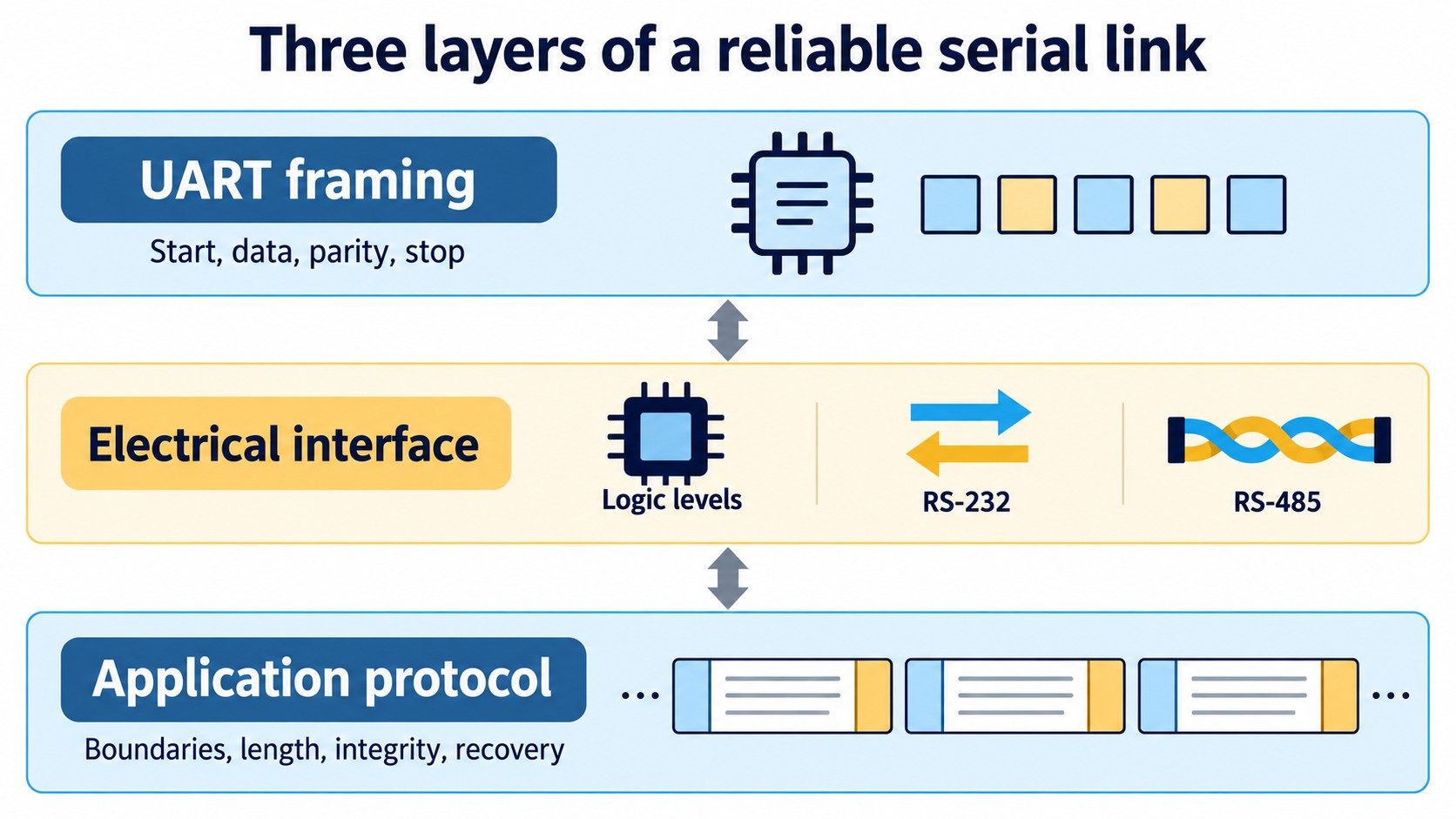
UART, logic levels, RS-232 and RS-485 describe different things
A UART peripheral handles serialization and reception. It does not make its pins electrically compatible with every connector called a serial port. A logic-level UART connection uses the relevant devices' digital input and output specifications. RS-232 and RS-485 add different electrical interfaces; neither should be wired directly to a conventional logic-level MCU UART pin without the appropriate transceiver.
| Interface choice | Function in the signal path | Check that remains necessary |
|---|---|---|
| Logic-level UART | Transfers serial logic between compatible devices | Input thresholds, output levels, input limits and reference connection |
| USB-to-UART bridge | Transfers data between USB and UART domains | Driver/configuration, UART voltage domain and buffering |
| RS-232 transceiver | Converts logic signals to and from RS-232 signaling | Charge-pump circuit, connector convention and supported conditions |
| RS-485 transceiver | Drives and receives a differential bus | Bus topology, common-mode range, termination and direction control |
Texas Instruments describes the MAX3232 as the electrical interface between an asynchronous communication controller and an RS-232 connector. Its charge pump and line drivers are part of that electrical conversion, not a replacement for the controller's UART. Source: TI MAX3232 datasheet.
RS-485 is similarly an electrical-layer specification. Message addressing, bus ownership and retries belong to the protocol and system using it. A UART byte stream can be transported through an RS-485 transceiver, but that does not automatically create a complete network protocol. Source: TI RS-485 Design Guide.
Check thresholds and power states before crossing TX and RX
For a conventional two-device, non-isolated logic connection, connect one device's TX output to the other device's RX input and establish the intended signal reference. Verify the actual board labels: a connector may name a signal from the board's perspective or from the equipment intended to plug into it.
Compare the transmitter's guaranteed HIGH and LOW output levels with the receiver's HIGH and LOW input requirements under the relevant supply, loading and temperature conditions. Separately check absolute-maximum input limits. A connection that recognizes logic correctly can still violate a pin's permitted voltage.
Do not interpret “TTL UART,” an adapter jumper label or a shared nominal supply as proof of compatibility. Check what an adapter's selector actually changes: its power output, its signal levels or both. Do not connect the adapter's supply pin unless the target's power arrangement calls for it.
Include powered-off and reset conditions in the review. If one endpoint remains powered while the other is off, check the receiving device's documented powered-off input behavior and possible current paths. For an isolated interface, follow the isolation and bus-side reference design instead of adding a ground wire across the barrier by habit.
Read an 8N1 frame before choosing the baud rate
Ten transmitted bits carry one eight-bit data character
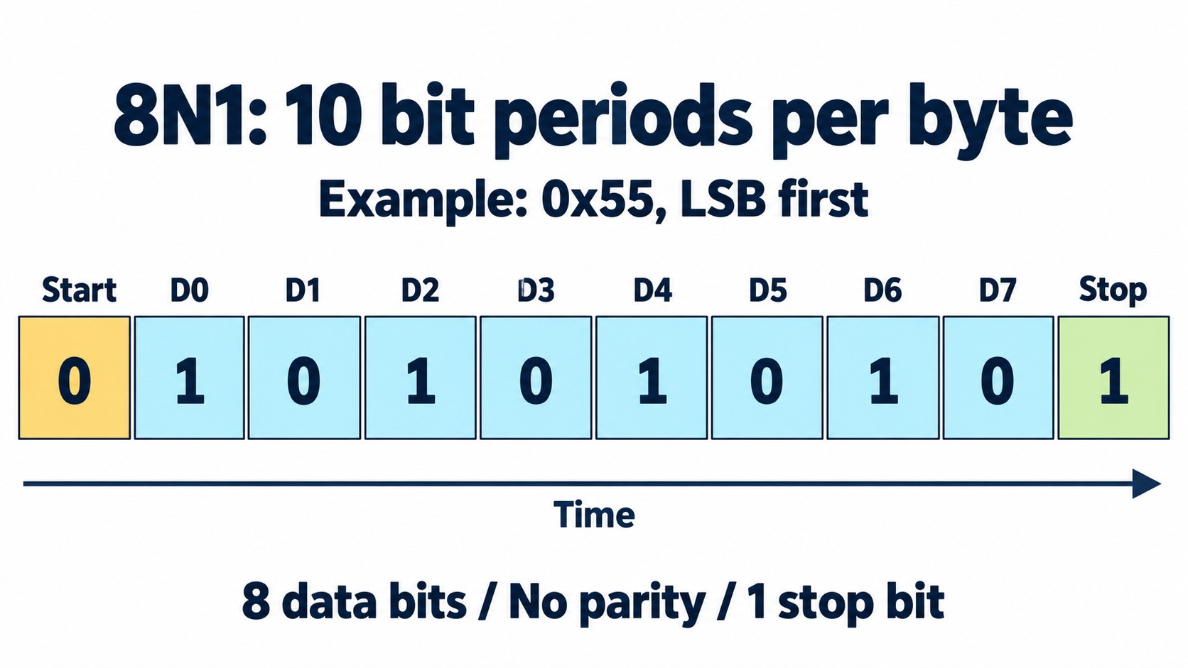
In conventional non-inverted 8N1 signaling, the line idles HIGH, a LOW start bit begins the character, eight data bits follow, and a HIGH stop bit ends it. The “N” means no parity bit. With least-significant-bit-first ordering, the first data bit on the wire is bit zero of the byte.
TI's UART protocol overview illustrates the start, data, optional parity and stop fields, with data shown from LSB to MSB. Check the actual controller before enabling inversion, another word length or an alternative bit order. Source: TI UART protocol overview.
For example, the byte 0x55 is binary 01010101 when written most-significant bit first. Its eight data bits are transmitted as 1, 0, 1, 0, 1, 0, 1, 0 in the conventional LSB-first mode. Including framing, the ten bit cells are:
Start 0 | D0 1 | D1 0 | D2 1 | D3 0 | D4 1 | D5 0 | D6 1 | D7 0 | Stop 1
This pattern is useful for measuring bit timing because it creates frequent transitions. It is a test pattern, not proof that every byte pattern or application message will work.
Parity is a check on a character, not a packet integrity scheme
With even parity, the combined number of one bits in the data and parity bit is even; with odd parity, it is odd. The byte 0x41 contains two one bits, so its even parity bit is 0 and its odd parity bit is 1. In 8N1, neither is transmitted because parity is disabled.
Parity can flag a character whose received parity differs from the configured rule. It cannot identify the damaged bit or correct it, and a change involving an even number of checked bits can preserve parity. Application messages therefore need their own integrity and recovery rules when the consequences of corrupted data require them. See TI's UART protocol and error overview.
Adding a parity bit changes the wire budget. An 8E1 character occupies eleven bit periods: one start, eight data, one even-parity bit and one stop. Extra stop time also increases character duration. It is not a general repair for incompatible levels, an unsuitable clock budget, lost bytes or noise on data bits.
Budget baud-rate error across both endpoints
Match the intended rate and check the generated rate
Both endpoints should be configured for the intended baud rate and compatible framing. Their physical clocks will have finite error. The receiver must still sample within valid portions of each character, allowing for its sampling method, start detection and the actual signal edges.
Analog Devices analyzes a 16-times-oversampling example in which the receiver synchronizes at each start bit. Its approximately ±2% and ±3.3% mismatch budgets follow different assumed valid sampling windows. Those are shared link budgets for that analysis, not a universal allowance for each UART. Source: Determining Clock Accuracy Requirements for UART Communications.
Use the selected controller's documented limits and operating mode. Account for oscillator tolerance over the required temperature range, baud-divider rounding, clock-tree configuration and any relevant calibration behavior. A terminal displaying “115200” establishes the requested setting; it does not measure either endpoint's bit period.
Avoid spending the same timing margin twice
As an illustrative calculation, suppose one endpoint actually produces 1.01 × B and the other 0.99 × B, where B is the intended rate. Comparing the faster endpoint with the slower one gives:
relative rate difference = (1.01 / 0.99 − 1) × 100% ≈ 2.02%
The small-error approximation is about 2%, not 1%. This arithmetic does not establish that the link will pass: receiver tolerance, quantization and signal quality still have to fit the design's budget. Measure both directions, since the two receivers and their operating modes may differ.
If communication fails only after a clock-frequency change or power mode transition, inspect the peripheral clock and baud configuration before replacing a transceiver. If it fails only at temperature extremes, include the documented oscillator behavior and measured signal timing in the investigation.
Calculate throughput and the receive-service deadline
Baud rate is not useful payload bytes per second
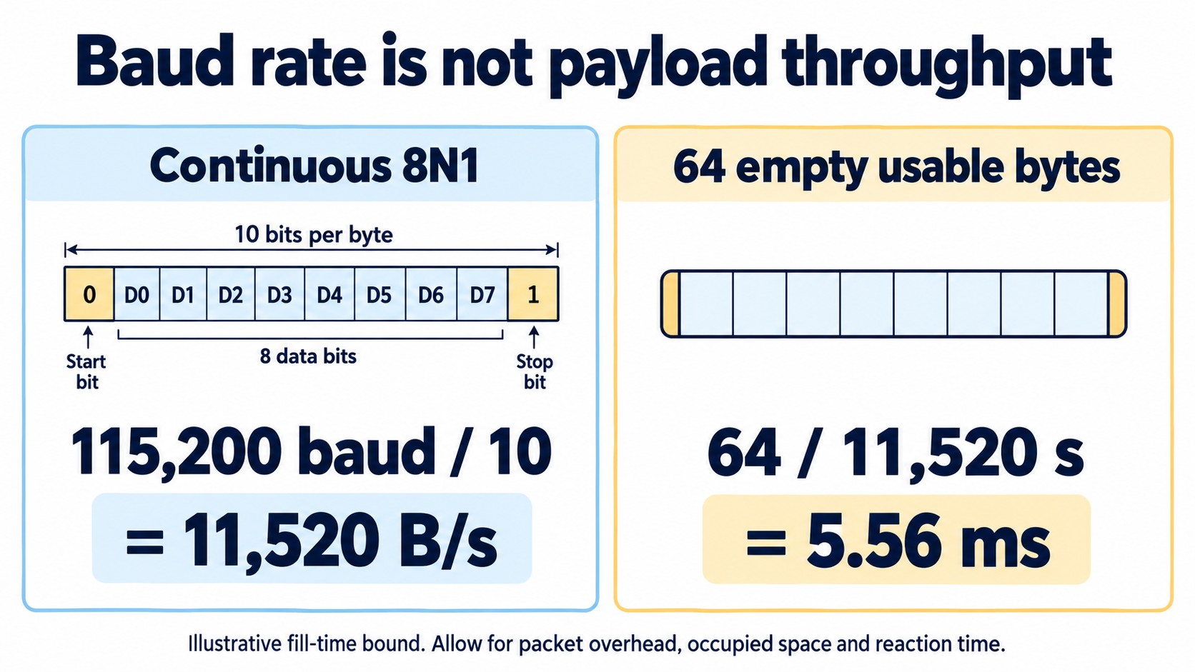
For ordinary binary UART signaling, one bit is carried per symbol. The baud value is therefore numerically the wire bit rate. For an uninterrupted 8N1 stream, the ideal character rate is:
character rate = baud rate / (1 + 8 + 0 + 1)
115200 / 10 = 11520 eight-bit characters per second
That is 11,520 bytes per second of character data before application headers, checks, gaps or flow-control pauses. It is not 115,200 bytes per second. Treat text formatting as traffic too: sending a numeric value as decimal text may require several characters plus separators and a line ending.
Consider a hypothetical, continuously repeated packet containing 52 payload bytes and 12 bytes of headers and checks. All 64 bytes use 8N1 framing. With no gaps or pauses, the payload ceiling is:
payload rate = 11520 × (52 / 64) = 9360 bytes per second
This is arithmetic for the stated packet format, not measured throughput of a USB bridge, operating system or MCU driver. Host scheduling and application processing can reduce useful throughput further. For block timing, 1,024 8N1 characters alone occupy about 88.9 ms at 115,200 baud.
Size buffers from free space and worst-case delay
At the same continuous character rate, a completely empty buffer with 64 usable byte positions fills in:
fill time = 64 / 11520 ≈ 0.00556 s = 5.56 ms
This is a fill-time bound under the stated assumptions, not a safe service deadline. A ring buffer may reserve a slot; some space may already be occupied; a burst may arrive while interrupts are delayed. Count usable free capacity at the point that matters, not the array's declared size.
Measure the longest interval during which software cannot drain or process incoming data. Include critical sections, higher-priority work and downstream stalls. DMA can move characters without a CPU read per character, but its destination can still fill if the consumer stops.
Reserve headroom for flow-control reaction
A receiver asserting a stop request does not erase characters already committed to the path. Establish how quickly the other transmitter responds, what it can finish sending, and whether bridge, driver or line buffers add traffic after the request.
A useful planning expression is:
required headroom ≥ ceil(character rate × stop-response time) + additional in-flight bytes + design margin
Define the terms so that the same bytes are not counted twice. For an illustrative 1 ms stop-response interval at 11,520 characters/s, four additional bytes not included in that interval and a four-byte margin, the expression gives 12 + 4 + 4 = 20 bytes. Those assumed quantities are not an RTS threshold recommendation for any specific IC.
For RTS/CTS, verify signal direction, active polarity, threshold behavior and stopping latency in both devices' documentation. Configure both ends consistently. An unused control input in the wrong state can stop traffic even when TX/RX wiring and baud settings are correct.
Treat RS-485 direction control as part of transmission
An RS-485 half-duplex link needs a rule for which node may drive the shared bus. The UART's transmit queue and the transceiver's driver enable are separate state machines that must agree about when a message starts and finishes.
Do not deassert driver enable merely because a data register can accept another byte or a software queue has become empty. The last character can still be in the shift register. Use the controller's documented indication that the final stop bit has left the transmitter, then account for the transceiver's enable/disable timing and the protocol's turnaround requirement.
In the Microchip peripheral example, transmit-buffer availability and transmitter-empty status are distinct. The exact flag names and clearing procedure are implementation-specific; a driver for another MCU must use that MCU's documented semantics. Source: Microchip UART manual, transmit operation.
For a selected transceiver, also check receiver-enable behavior during local transmission, idle-bus behavior and the allowed common-mode range. Termination and any bias network should follow the actual cable, topology, receiver characteristics and system requirements. A headline data rate or a quoted cable length does not approve the installed bus.
For a deeper investigation of the bus itself, use the RS-485 troubleshooting guide. Keep that physical-layer investigation distinct from a parser that drops an otherwise correctly received byte.
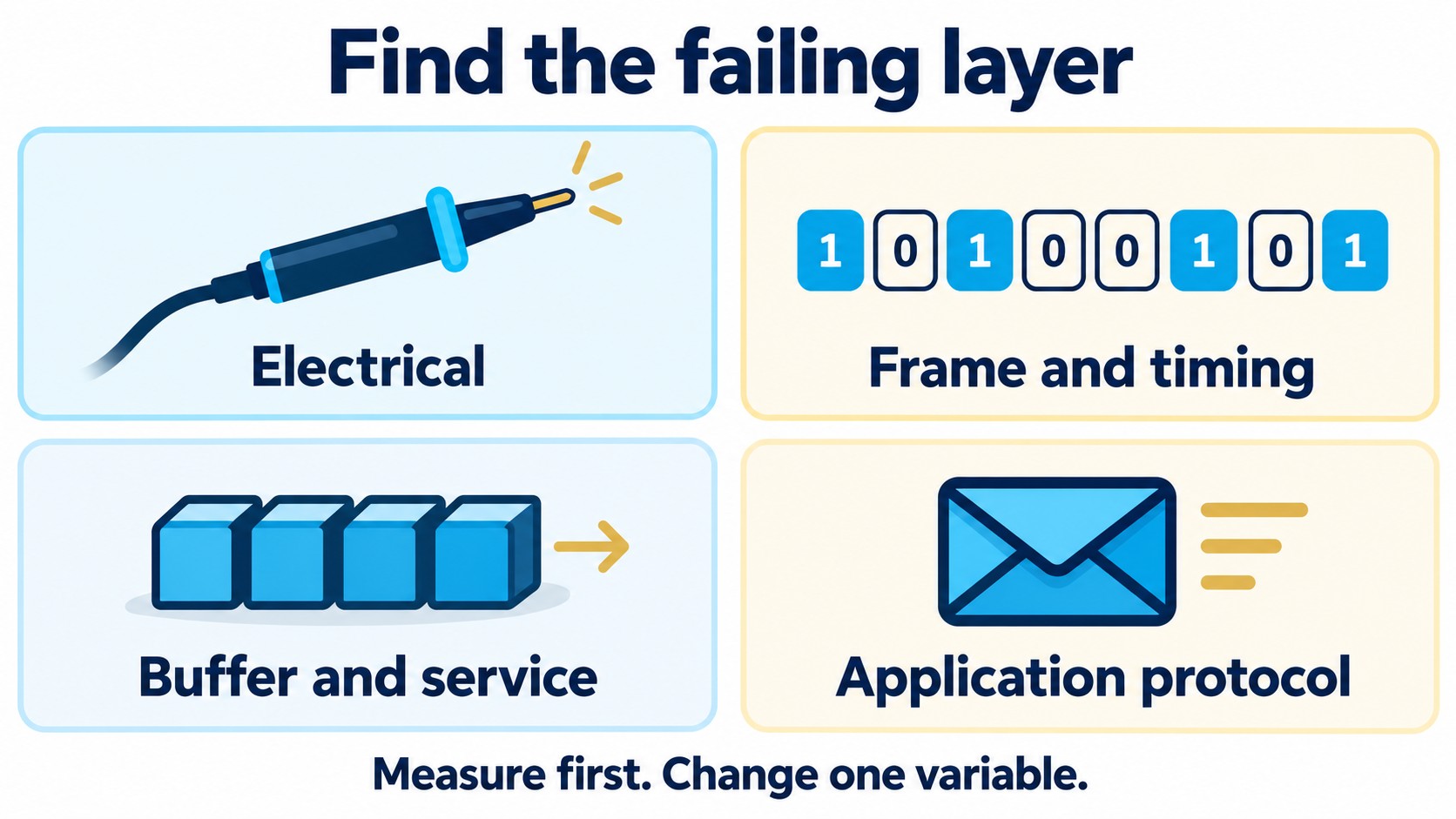
Troubleshoot UART with evidence from the failing layer
Distinguish a bad character from a lost character
A framing error indicates that a received character failed the peripheral's framing check, commonly involving the expected stop level. A parity error reports a parity mismatch when that check is enabled. An overrun indicates that receive storage could not accept incoming data under that peripheral's documented conditions.
These categories lead to different tests. A clean oscilloscope trace does not rule out an overrun caused by delayed software service. A buffer that is large enough does not repair incorrect voltage thresholds. Read and log the device's error indications before a recovery sequence clears the evidence.
| Observation | Evidence to collect | Next check |
|---|---|---|
| No activity at the receiving pin | Waveform at the intended TX and RX test points | Pin multiplexing, wiring, reset state and any disabled transceiver |
| Activity but consistently wrong characters | Bit period, polarity and decoded frame settings | Actual baud rate, data length, parity and logic levels |
| Missing bytes during bursts | Error counters, buffer occupancy and service latency | Hardware FIFO, software ring buffer and flow-control reaction |
| Last byte damaged on a half-duplex bus | Final stop bit versus driver-enable edge | True transmission completion and bus turnaround |
| Characters are correct but packets are rejected | Raw byte log and parser decisions | Length, delimiters, escaping, integrity check and timeout rules |
| Failure after reset or a power transition | Pin levels and clock/configuration sequence | Startup ordering, boot messages and powered-off interfaces |
In the documented dsPIC33E/PIC24E example, an overrun can inhibit further reception until software follows the prescribed recovery procedure. Do not transplant that exact behavior or recovery sequence to every UART. Read the selected peripheral's error-handling section. Source: Microchip UART manual, receive errors.
Use loopback tests to locate a boundary
Write down where a loopback is connected. An internal peripheral loopback, a bridge's logic-level TX-to-RX loop and a test through an external cable exercise different paths. Passing one does not certify hardware outside that loop.
Start with known repeated bytes and inspect the timing and voltage at the actual receiving pin. Then send mixed patterns and sustained bursts with recorded counts. Finally test the application packet format, recovery after an interrupted message and the required power/reset transitions.
Change one variable at a time. If lowering baud rate makes the failure disappear, investigate the evidence rather than concluding that the UART has a universal speed limit. More timing margin, less signal distortion or a lower incoming-byte rate can each explain that result.
Select the bridge or transceiver for its actual role
The following parts illustrate three different functions. They are not substitutes for one another, and a package match or a family-level product description does not establish complete compatibility.
| Role | Complete ordering-code example | Mechanical check | What the role does not solve |
|---|---|---|---|
| USB-to-UART bridge | CP2102N-A02-GQFN28R | QFN-28; verify the exact package drawing | Does not itself provide RS-232 or RS-485 line signaling |
| RS-232 electrical interface | MAX3232IDBR | SSOP-16, TI DB package | Does not create UART framing or an application protocol |
| Half-duplex RS-485 transceiver | SN65HVD75DR | SOIC-8, TI D package | Does not allocate bus ownership or validate application packets |
The Silicon Labs CP2102N family combines USB and UART functions, but its USB signaling rate is not its UART payload rate. Its package variants also differ: do not apply a separate VIO-pin configuration from another package to the QFN-28 device. Check the exact revision and package-specific electrical tables. See the CP2102N datasheet and the CP2102N package and design guide.
For the TI RS-232 example, the full IDBR ordering code identifies the SSOP package option listed in the manufacturer's ordering information. Package suffixes are procurement and assembly information; they should not be shortened away when the board requires a specific footprint.
For the SN65HVD75 example, driver and receiver enables must be controlled according to the device's truth table. Its differential bus specifications and logic-side requirements are separate checks. Use the TI SN65HVD75 datasheet for electrical and switching conditions instead of applying a generic “RS-485 compatible” label.
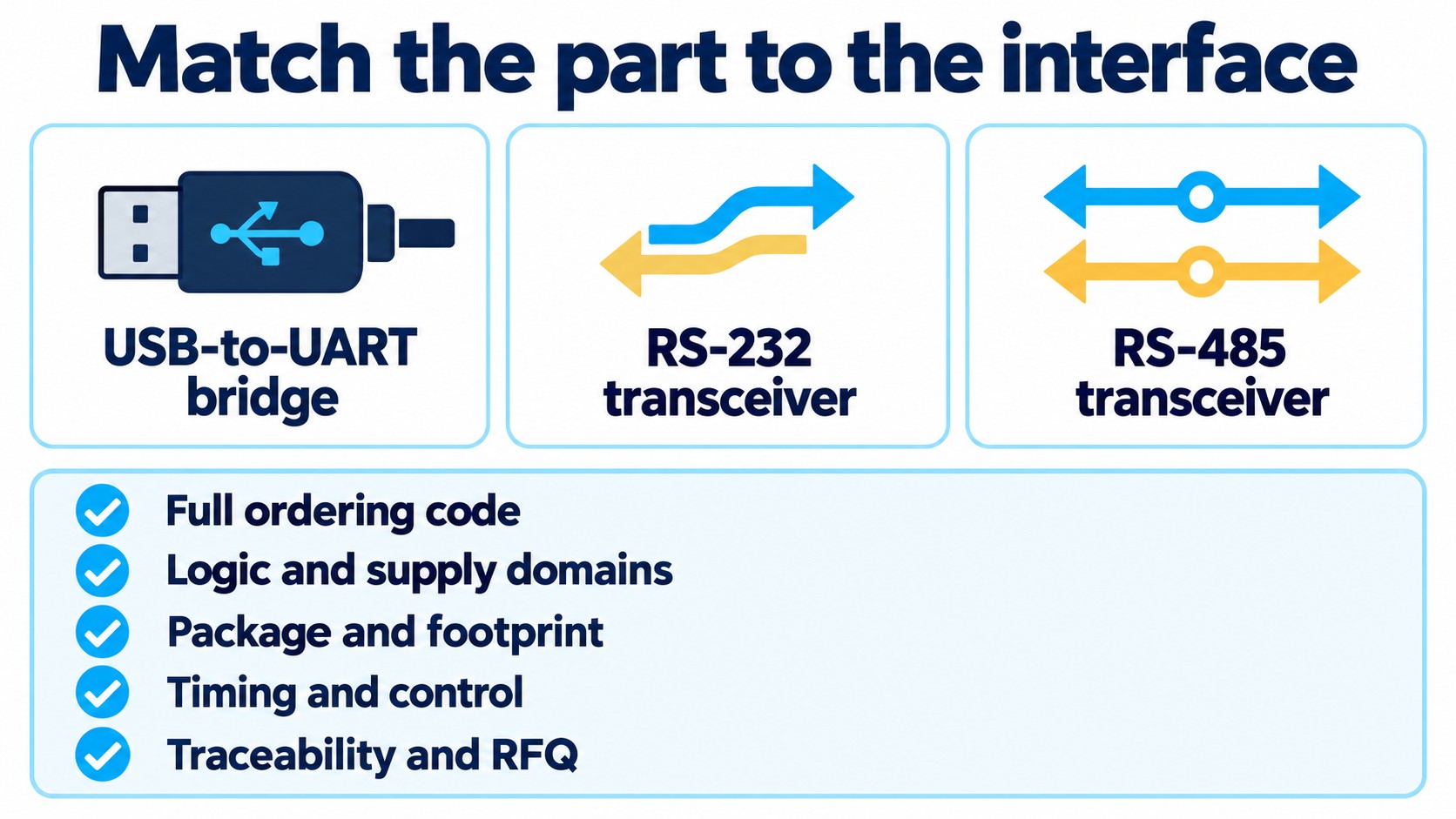
Before releasing the BOM, confirm the full manufacturer part number, supply and logic domains, package dimensions and land pattern, temperature requirements, software/configuration dependencies and documented lifecycle. Confirm availability, packing, price and lead time during the RFQ; this guide does not establish those commercial facts.
Record an interface contract before approving the board
A useful UART handoff is specific enough for another engineer to reproduce the link. Record which endpoint owns each signal name, the electrical interface, supplies and reference arrangement, frame format, intended and generated baud rates, control-line behavior and any half-duplex turnaround rules.
Then record the traffic assumptions: maximum packet size, sustained and burst rates, usable buffer capacity, longest service interruption and permitted response to overflow. State whether loss is acceptable and how a sender or receiver can detect and recover from it.
At the application layer, define message boundaries and lengths, byte ordering for multi-byte values, integrity-check details where required, timeout behavior and recovery after a partial message. A CRC name alone is insufficient for interoperability: implementations must agree the selected algorithm's parameters and which bytes it covers.
Use a short release checklist:
- Verify pin multiplexing, electrical limits and power/reset states against the actual schematics and datasheets.
- Measure timing and signal levels in both directions under the required operating conditions.
- Run sustained and burst traffic while observing error counts, occupancy and service latency.
- Exercise flow control or half-duplex turnaround, including the last transmitted stop bit.
- Test application recovery after a damaged, missing or interrupted message.
- Preserve the exact BOM codes, configuration and test conditions with the approval record.
If the project includes a wireless module, the ESP32 hardware guide covers the adjacent power and boot checks. For procurement, submit the complete interface requirement and BOM for an RFQ once the electrical and software roles are clear.
Frequently asked questions about UART communication
Is UART the same as TTL?
No. UART describes a peripheral and its serial framing. TTL refers to a logic family and associated electrical characteristics. A board labeled “TTL serial” still requires verification of the actual HIGH/LOW levels, permitted input voltage and reference connection.
Can a 5 V UART connect directly to a 3.3 V UART?
Only if both directions meet the relevant devices' electrical requirements. Check output levels, input thresholds and input-voltage limits, including powered-off conditions. A 3.3 V supply label does not establish that an input tolerates 5 V, and input tolerance does not guarantee the reverse direction's logic margin.
Does 115200 baud mean 115200 bytes per second?
No. An 8N1 character occupies ten wire bit periods, so a continuous stream at 115,200 baud carries at most 11,520 eight-bit characters per second before application overhead and pauses. Add parity, stop time or packet overhead to calculate the useful payload rate.
Will two stop bits fix a noisy UART connection?
Not as a general solution. Additional stop time changes framing and reduces character rate, but it does not correct a damaged data bit or an electrical mismatch. Establish whether the observed failure is framing, parity, overrun or application parsing, then test its cause.
Does UART need a shared clock?
Conventional asynchronous UART uses no shared clock signal between endpoints. Each endpoint still needs a local timing source accurate enough for the selected receiver and link conditions. Start-bit synchronization provides a reference for receiving each character; it does not remove clock-error limits.
Does an RS-485 transceiver make a UART into Modbus?
No. A transceiver provides the electrical interface. A complete Modbus implementation also requires the specified message format, addressing, timing, checks and software behavior. The same distinction applies to a custom protocol carried over an RS-485 link.