
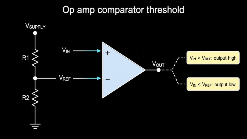
An op amp comparator is a simple voltage decision circuit. It compares an input voltage with a reference voltage. If the input is above the reference, the output changes to one state. If the input is below the reference, the output changes to the other state.
This is useful for voltage detection, battery monitors, sensor thresholds, zero-crossing checks, and simple control signals. But there is one important rule: an op amp is not the same part as a dedicated comparator IC. An op amp can work as a comparator in slow, low-risk circuits, but a real comparator IC is usually better when you need fast switching, clean logic output, defined propagation delay, wide input overdrive behavior, or stable operation near the threshold.
For procurement, do not choose only by package or price. Check the input range, output type, recovery from saturation, speed, hysteresis needs, and logic interface before sending an RFQ or approving a BOM.
What Is an Op Amp Comparator?
An op amp comparator uses an operational amplifier without normal negative feedback. The op amp works open loop, so its high gain makes the output move hard toward one rail or the other.
In a basic non-inverting comparator:
| Condition | Output Action | Design Meaning |
|---|---|---|
| VIN is higher than VREF | Output goes high, or toward the positive rail | The input passed the set threshold |
| VIN is lower than VREF | Output goes low, or toward the negative rail | The input is below the set threshold |
In a basic inverting comparator, the input and reference positions are swapped, so the output logic is reversed.
This makes the circuit easy to understand, but the output level is not always a clean logic level. Many op amps have push-pull outputs that swing near their own supply rails. If the next device uses 3.3 V logic and the op amp runs from 12 V, the output may need level shifting or protection.
Comparator Using Op Amp: Basic Threshold Design
The reference voltage sets the trip point. A common way to create VREF is a resistor divider:
VREF = VSUPPLY x R2 / (R1 + R2)
Use this only as a starting point. A real design also needs to check resistor tolerance, input bias current, input offset voltage, noise, and the allowed common-mode input range.
| Application | What the Comparator Checks | Buyer / BOM Note |
|---|---|---|
| Battery low warning | Battery divider voltage vs reference | Verify current draw and reference tolerance |
| Temperature limit | Sensor voltage vs limit voltage | Check sensor noise and slow crossing |
| Overvoltage detect | Scaled rail voltage vs reference | Use correct input protection and voltage rating |
| Zero-crossing detector | AC signal crossing a reference point | Keep this as a separate owner topic from this article |
| Window detector | Signal between upper and lower limits | Needs two comparators or a suitable comparator IC |
Inverting and Non-Inverting Comparator
The difference is which input receives the signal.
| Type | Signal Input | Reference Input | Output Behavior |
|---|---|---|---|
| Non-inverting comparator | + input | - input | Output goes high when VIN is above VREF |
| Inverting comparator | - input | + input | Output goes high when VIN is below VREF |
This choice matters for the logic device after the comparator. If the comparator output drives an MCU interrupt, enable pin, transistor, MOSFET gate driver, or power-good signal, confirm the required active-high or active-low logic before choosing the circuit.
Why Hysteresis Is Often Needed
A simple op amp comparator has one threshold. If the input is slow or noisy, the signal can cross the threshold many times. The output may chatter, which means it rapidly switches high and low near the trip point.
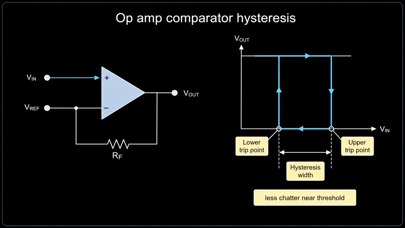
Hysteresis solves this by creating two thresholds:
| Term | Meaning |
|---|---|
| Upper trip point | The voltage where the output switches in one direction |
| Lower trip point | The voltage where the output switches back |
| Hysteresis width | The voltage gap between the two trip points |
Hysteresis is made with positive feedback. After the output changes state, the feedback moves the effective reference point. The input must move farther in the opposite direction before the output can switch back. This helps battery monitors, temperature sensors, light sensors, and other slow signals.
Use the separate Schmitt trigger page for the full timing and waveform topic: op amp Schmitt trigger and hysteresis. This op amp comparator article should not own multivibrator, astable, or monostable timing intent. Those need separate timing pages.
Saturation Recovery: The Common Hidden Problem
When an op amp is used as a comparator, the output is usually driven into saturation. Many op amps are designed for linear closed-loop operation, not for repeated hard switching. After saturation, the op amp may take longer to recover before it can respond correctly to the next input change.

This is why a comparator using op amp can look fine in a slow bench test but fail in a faster system. Saturation recovery may not be fully specified in the op amp datasheet. If switching time matters, use a comparator IC with specified propagation delay, overdrive conditions, and output behavior.
| Check | Why It Matters |
|---|---|
| Is the input signal slow or fast? | Slow signals need hysteresis; fast signals need propagation delay data |
| Does the op amp output hit the rail? | Rail saturation can slow recovery |
| Is recovery time specified? | If not, lab testing and design margin are needed |
| Does the next device need logic levels? | A dedicated comparator output may be easier to interface |
| Is the circuit safety-critical? | Use a comparator IC with clear datasheet limits |
When an Op Amp Comparator Is Acceptable
An op amp can be acceptable as a comparator when all of these are true:
- The signal changes slowly.
- The circuit is not timing-critical.
- The input stays inside the allowed common-mode range.
- The output voltage is safe for the next device.
- Hysteresis or filtering handles noise.
- Bench testing covers the expected input overdrive and temperature range.
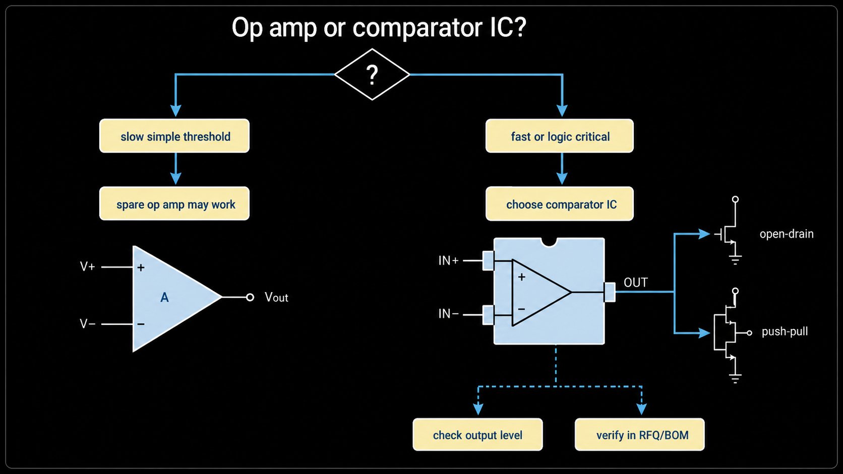
This can be practical when a spare op amp channel is already available in the design and the comparison is simple, slow, and low risk.
When to Use a Real Comparator IC
Use a dedicated comparator IC when the design needs any of the following:
| Requirement | Why a Comparator IC Is Better |
|---|---|
| Fast edge or known delay | Comparator datasheets specify propagation delay under overdrive conditions |
| Logic interface | Many comparators offer open-drain, open-collector, or push-pull logic outputs |
| Noisy threshold | Some comparator ICs include internal hysteresis |
| Large input difference | Comparator input stages are built for open-loop comparison |
| Low power detection | Many comparator ICs are made for always-on monitoring |
| Safety or control loop | Defined switching behavior reduces risk |
Examples of real comparator families include LM393-type dual comparators and LM339-type quad comparators. Do not assume an LM358, LM324, LM741, TL072, or LF353 is a drop-in comparator IC. They are op amps first. If a BOM uses one as a comparator, review the circuit conditions before approving substitution.
Window Comparator, ZCD, and Other Related Topics
This article owns the core op amp comparator topic. It should link to, but not replace, these related pages:
| Related Search Intent | Owner URL | Reason |
|---|---|---|
| Window comparator using op amp | /blog/window-comparator-using-op-amp/ | Uses upper and lower thresholds, normally needs two comparators |
| Zero-crossing detector using op amp | /blog/zero-crossing-detector-using-op-amp/ | Focuses on AC crossing, noise, protection, and output timing |
| Schmitt trigger using op amp | /blog/op-amp-schmitt-trigger-hysteresis/ | Owns hysteresis equations and waveform shaping |
| Monostable or multivibrator timing | /blog/op-amp-monostable-multivibrator/ | Owns pulse timing and RC timing behavior |
| Comparator IC sourcing | /products/comparators/ | Owns product discovery, package, output type, and RFQ |
Keeping these owner URLs separate reduces keyword cannibalization and makes the site easier for engineers and buyers to use.
Selection Checklist for BOM and RFQ
| Item | What to Verify |
|---|---|
| Threshold | VREF value, tolerance, temperature drift, and resistor tolerance |
| Input range | Common-mode range and maximum differential input voltage |
| Output | Rail swing, open-drain/open-collector, push-pull, pull-up voltage, logic compatibility |
| Speed | Propagation delay, slew rate, overdrive, and recovery from saturation |
| Noise | Need for hysteresis, filtering, layout care, and reference bypassing |
| Supply | Single-supply or dual-supply operation and power budget |
| Package | Footprint, pinout, assembly process, and thermal environment |
| Lifecycle | Active, NRND, EOL, or substitute risk |
| Compliance | RoHS, REACH, AEC-Q, UL, or other project requirements only after source verification |
| Availability | Stock, price, lead time, and authorized-channel status must be confirmed by RFQ or BOM review |
Common Mistakes
Mistake 1: Treating Any Op Amp as a Comparator IC
An op amp may compare two voltages, but it is not optimized for that job. It may recover slowly from saturation, have input behavior that changes outside linear operation, and produce output levels that do not match the logic rail.
Mistake 2: Forgetting Hysteresis
If the input moves slowly through the threshold, even small noise can cause chatter. Add hysteresis or choose a comparator with internal hysteresis.
Mistake 3: Ignoring Output Interface
A comparator output may be open-drain or open-collector and need a pull-up resistor. An op amp output may swing near its own supply rail. Check the next device before connecting the output directly.
Mistake 4: Letting This Article Own Timing Topics
Schmitt triggers, window comparators, zero-crossing detectors, multivibrators, and monostable circuits deserve their own pages. This article should explain the core comparator decision and link to those topics.
Request Quote / Upload BOM
If your BOM includes an op amp used as a comparator, send us the part number, supply voltage, input signal range, threshold voltage, output load, and switching-speed requirement. We can help check whether the op amp is suitable or whether a comparator IC is the better sourcing path.
For multi-part projects, use Upload BOM so we can review availability, package, lifecycle, substitute risk, and RFQ details. For a single comparator or op amp line item, use Request Quote and include the target quantity and required delivery window. Stock, price, lead time, certification, and authorized-channel status must be verified during RFQ.
FAQ
Can I use an op amp as a comparator?
Yes, but only when the signal is slow, the output level is safe, and the design can handle saturation recovery and noise. For fast, noisy, or logic-critical circuits, use a real comparator IC.
What is the threshold in an op amp comparator?
The threshold is the reference voltage that the input is compared against. It can come from a resistor divider, reference IC, DAC, zener reference, or another signal source.
Why does an op amp comparator need hysteresis?
Hysteresis adds two switching points instead of one. It prevents repeated output switching when a noisy or slow signal stays near the threshold.
Is LM358 a comparator IC?
No. LM358 is an operational amplifier. It can be used as a slow comparator in some circuits, but it is not a dedicated comparator IC. Review common-mode range, output swing, speed, and recovery behavior before using or replacing it.
When should I choose LM393 or another comparator IC instead?
Choose a comparator IC when you need specified propagation delay, open-drain or open-collector logic output, better threshold behavior, internal hysteresis, or more reliable switching than a general op amp can provide.
External Sources
- Analog Devices, "MT-084: Using Op Amps as Comparators": https://www.analog.com/MT-084
- Analog Devices, "Amplifiers as Comparators?": https://www.analog.com/en/resources/analog-dialogue/articles/amplifiers-as-comparators.html
- Analog Devices, "Curing Comparator Instability with Hysteresis": https://www.analog.com/en/resources/analog-dialogue/articles/curing-comparator-instability-with-hysteresis.html
- Texas Instruments, "Solving top comparator challenges: Chatter": https://www.ti.com/document-viewer/lit/html/SSZT122
- Texas Instruments, "Comparator with and without hysteresis circuit": https://www.ti.com/lit/an/sboa219a/sboa219a.pdf
- Texas Instruments, LM393B datasheet: https://www.ti.com/lit/ds/symlink/lm393b.pdf

Alice lee
Business Manager
Focused on the electronic components sector, the author shares industry knowledge, product insights, and sourcing perspectives related to modern electronics manufacturing. With close attention to market trends, component applications, and supply chain developments, the content is designed to support engineers, buyers, and businesses in making more informed decisions.