
No products in the cart.
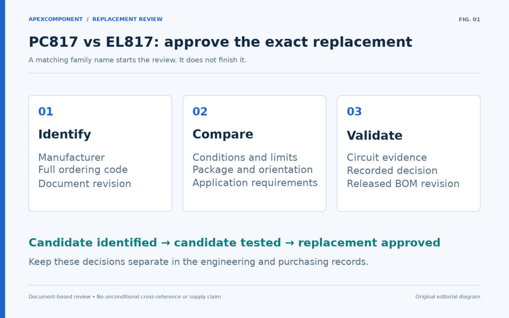
An EL817 can be a candidate replacement for a PC817, but the family names do not establish interchangeability. Approval needs the manufacturer, complete ordering code, electrical conditions, package drawing and evidence from the intended circuit. Begin by identifying the fitted part and the proposed replacement; then compare the requirements that matter to that design.
This guide works through Sharp PC817X3NSZ1B and Everlight EL817(C)-G as a document-based example. It gives engineering and purchasing teams a comparison table, a validation sequence and a sourcing checklist. It does not approve either device for an unspecified board.
Identify both parts before comparing them
A useful replacement request contains two records: what is currently approved and what is being proposed. Photograph the fitted device and packaging label, then check them against the BOM and purchasing record. A short top marking alone may not capture the original ordering option.
For this example, Sharp's model table identifies PC817X3NSZ1B as a through-hole, sleeve-packed C-rank part. Everlight's ordering scheme identifies EL817(C)-G as the standard DIP option with C rank; its V option is separate. The Everlight name here retains the parentheses used in that ordering scheme. See the Sharp model line-up and Everlight order information.
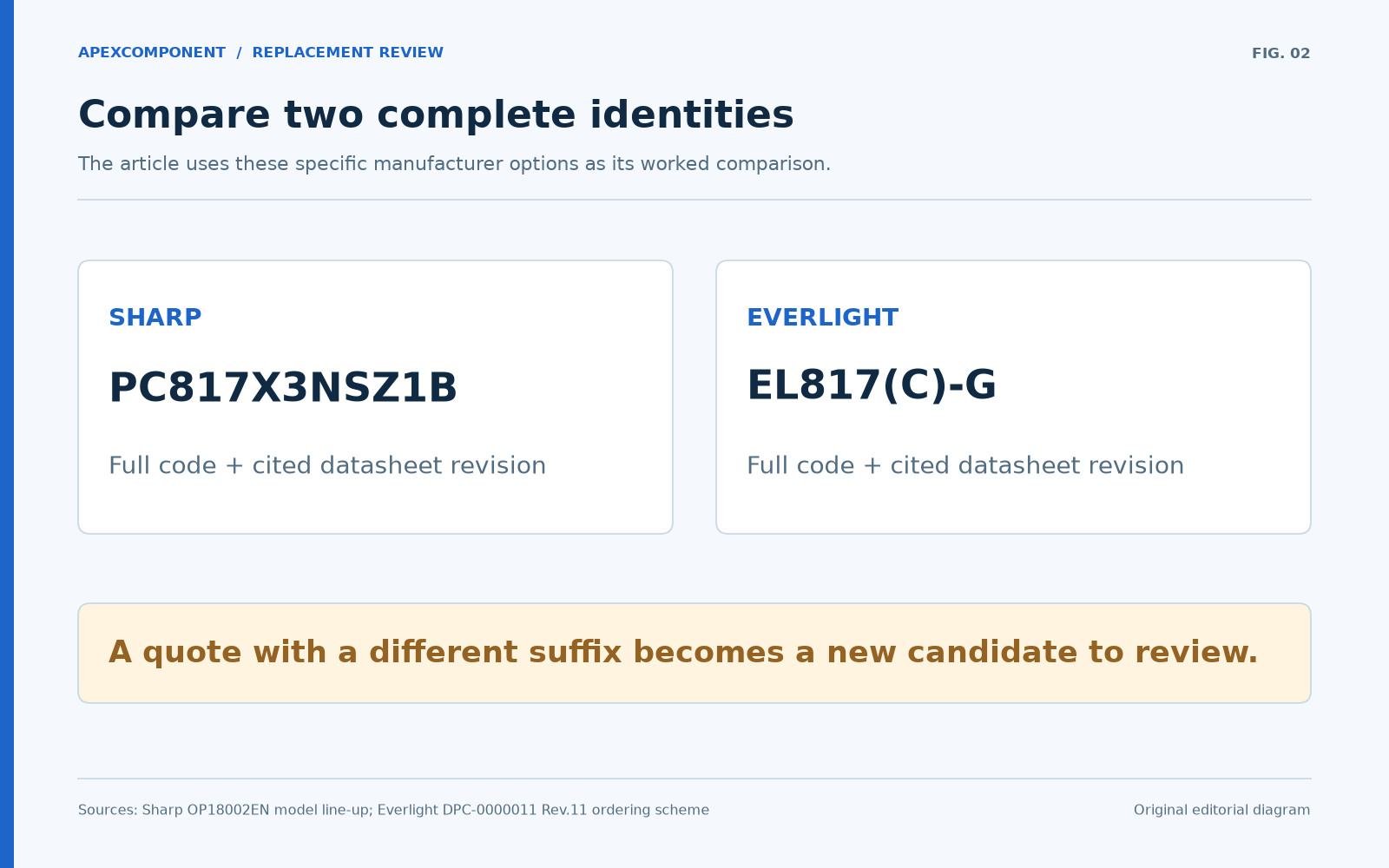
Do not transfer a suffix definition between manufacturers. Ask the supplier to return the complete manufacturer part number in the quotation and order acknowledgement. If it differs from the requested code, treat it as a new candidate for review, even when the description still says “817 optocoupler.”
PC817 vs EL817: compare the documented limits
The following is a selected comparison, not a complete specification. Electrical values are at Ta = 25°C unless a different condition is shown. The document-level sources are Sharp OP18002EN, January 15, 2018, pages 2, 4–5 and Everlight DPC-0000011 Rev.11, pages 1–3 and 6.
| Check | Sharp PC817X3NSZ1B | Everlight EL817(C)-G |
|---|---|---|
| Pin functions | 1 anode, 2 cathode, 3 emitter, 4 collector | Same functions |
| Selected rank at IF = 5 mA, VCE = 5 V | IC = 10–20 mA; derived CTR = 200–400% | CTR = 200–400% |
| VCEO absolute maximum | 80 V | 80 V |
| Continuous IF absolute maximum | 50 mA | 60 mA |
| Listed operating temperature | −30 to +100°C | −55 to +110°C |
| VCE(sat), maximum; IF = 20 mA, IC = 1 mA | 0.2 V | 0.2 V |
| Rise / fall time, typical | 4 / 3 µs | 6 / 8 µs |
| Rise / fall time, maximum | 18 / 18 µs | 18 / 18 µs |
| Timing conditions | VCE = 2 V, IC = 2 mA, RL = 100 Ω | Same conditions |
| Dark current, maximum | 100 nA at VCE = 50 V, IF = 0 | 100 nA at VCE = 20 V, IF = 0 |
The matched rows justify further evaluation. They do not establish identical behavior at every operating point. In particular, the leakage figures use different voltages, and a wider temperature rating does not establish the required transfer behavior throughout that range. Absolute maximum current is a limit, not a recommended LED drive setting.

The table also shows why broad claims such as “all PC817 parts have one voltage rating” are unsuitable for approval. Keep the exact document attached to the exact code. If a different PC817 variant or a non-G EL817 is offered, rebuild the comparison from its own specification.
Check the CTR range against the circuit load
Current transfer ratio is IC divided by IF, expressed as a percentage. Sharp's collector-current interval in the selected model row converts to the CTR interval shown above. This arithmetic interprets that test point; it does not extend the interval to a different LED current or collector voltage.
Vishay's transistor-output optocoupler FAQ explains that CTR bins are defined under specified conditions and that operating-point review uses the relevant device characteristics. For a detailed review of those conditions, see our CTR curves guide.
Start with the required current
For a simple pulled-up output, a preliminary load estimate is:
Irequired = (VPU,max − VOL,target) / RPU,min + Iother
As a hypothetical example, let VPU,max = 3.465 V, VOL,target = 0.4 V, RPU,min = 4.653 kΩ and additional current into the node = 20 µA. The transistor must sink approximately 0.679 mA. With minimum LED current of 2 mA, that corresponds to a required effective transfer ratio of 33.94% at the intended low-state operating point.
This is a requirement calculation, not a pass result for either candidate. The selected datasheet rank was measured at a different LED current and VCE. Record how you establish the available sink current at the actual conditions, including temperature and the design's service-life assumptions. Do not use the ratio between these unlike test points as a guaranteed margin.
Use the CTR guide's calculator to estimate the load requirement, then compare it with device-specific evidence at your operating point.
Review mechanical fit and the isolation requirement
Matching pin functions is only the first mechanical check. Compare the exact lead form, dimensions, tolerances, orientation and assembly process against the board drawing. Check body clearance and mounting constraints as well as the electrical net assignment. A family-level CAD model is insufficient if it represents a different package option.

Keep insulation qualification in a separate review. A matching isolation test voltage is not proof of an identical working-voltage rating or approval scope. Vishay distinguishes these isolation terms in FAQ questions 13–14.
For the application, obtain the relevant certificate and conditions for the actual ordering option, then compare them with the equipment requirements. Do not treat a supplier's generic family certificate as confirmation for every suffix. This article does not establish an equipment-level safety approval for either device.
Validate the function that the optocoupler performs
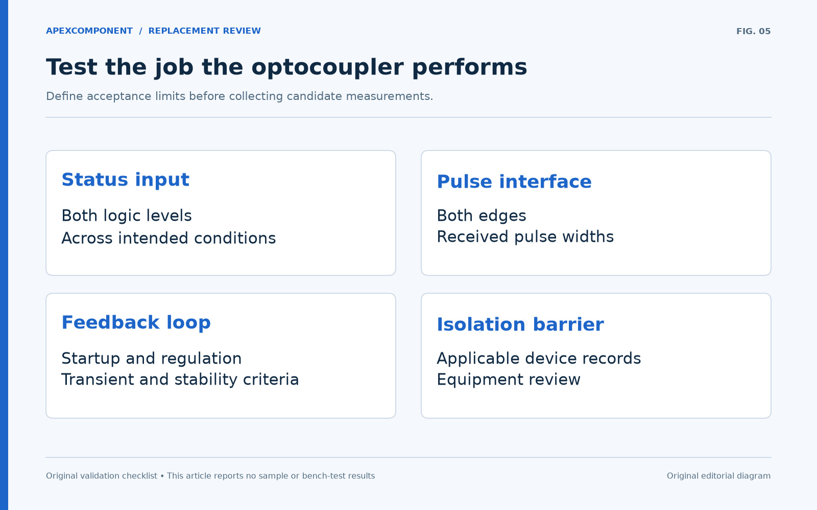
Define acceptance limits before comparing samples. Save the baseline configuration, schematic revision and original-device measurements so that the candidate is tested against the same task.
| Circuit role | Evidence to collect | What a simple static check misses |
|---|---|---|
| On/off status input | Both logic levels across supply, load and temperature conditions | Whether the receiver recognizes the transition on time |
| Pulse or digital interface | Both edges, received pulse widths and threshold crossings | Distortion that occurs even when final voltage levels look correct |
| Power-supply feedback path | Startup, regulation, transient response and the design's loop-stability criteria | Whether a replacement changes the closed-loop response |
| Equipment isolation barrier | Applicable device documentation and system review | Whether a functional signal test establishes the required insulation qualification |
For pulses, do not turn a small-signal cutoff-frequency number into a supported baud rate. Vishay defines cutoff frequency as a small-signal measurement around a DC operating point in FAQ question 10. Our turn-off delay guide gives the separate waveform and RC checks for a pulled-up output.
For feedback, do not assume that a higher CTR bin is an upgrade. Define the transfer range the control circuit needs, then evaluate the complete circuit. A part can satisfy a minimum-current requirement and still need a separate dynamic review.
Keep these three decisions distinct:
- Candidate identified: the code and documents are sufficiently clear to compare.
- Candidate tested: the recorded sample and circuit configuration meet the defined checks.
- Replacement approved: the responsible design or quality process has released the exact code for the specified assembly and revision.
If evidence is missing, record an open item and its owner. Avoid converting “no problem seen in one sample” into approval for all conditions or future deliveries.
Give the supplier a complete replacement request
A useful RFQ lets the supplier distinguish an exact reorder from an alternative proposal. Include:
- Original manufacturer and full part number, plus the assembly/BOM revision.
- Proposed candidate code, or permission to propose alternatives for evaluation.
- Required quantity, delivery location and requested date.
- Required lead form, packing and any certificate or traceability documents.
- The circuit role and the electrical or timing requirements that constrain selection.
- Whether substitution already has approval, and the approval reference if it does.

Ask for the offered code, supporting datasheet and any unresolved differences to be stated explicitly. Keep price, stock, lead time and production status as quote-specific fields; none is inferred from a datasheet being available online.
Download the replacement review worksheet (CSV) to record the original part, candidate, requirements, evidence and decision across 19 review items.
Keep a review record with separate fields for the original part, candidate, requirement, evidence and decision. Use the optocoupler selection page to organize the wider shortlist, then submit the BOM and replacement requirements.
Common replacement questions
Can I replace any PC817 with any EL817?
No family-wide approval follows from the names. Identify the exact manufacturer and ordering options, compare their documented limits, and validate the circuit's requirements before releasing the change.
Does matching the C rank settle the comparison?
It settles only the rank comparison under the stated conditions for the selected example. Package, operating point, timing and applicable qualification still need review. Rank names should be decoded in each manufacturer's own document.
Can a higher current or temperature rating justify the change?
It may remove one constraint, but it does not show that the replacement meets every functional requirement. Record which requirement the rating addresses and keep the remaining checks open.
Is a working prototype enough for purchasing to substitute the part?
Record what was tested, which samples and assembly revision were used, and who approved the change. Purchasing should order against that released record rather than a broad “PC817 equivalent” description.