
No products in the cart.

A digital isolator’s default output state is the logic level selected for a defined loss-of-input condition while the receiving side can still operate. It may be high or low, depending on the device. That description does not establish the output level when the receiving supply is also missing, during a supply ramp, or when the upstream controller remains powered but sends the wrong signal.
The useful design question is: what will the receiving circuit do in every relevant power state? Answer it channel by channel, using the exact part’s function table and the receiving circuit’s active polarity.
Start with the direction of each channel
Use two labels for the channel under review:
- Input-side supply: powers the circuitry that receives the external logic input.
- Output-side supply: powers the circuitry that drives the isolated logic output.
These labels describe a channel, not necessarily the left and right sides of the package. For a bidirectional isolator, they swap when you review a channel traveling in the opposite direction.
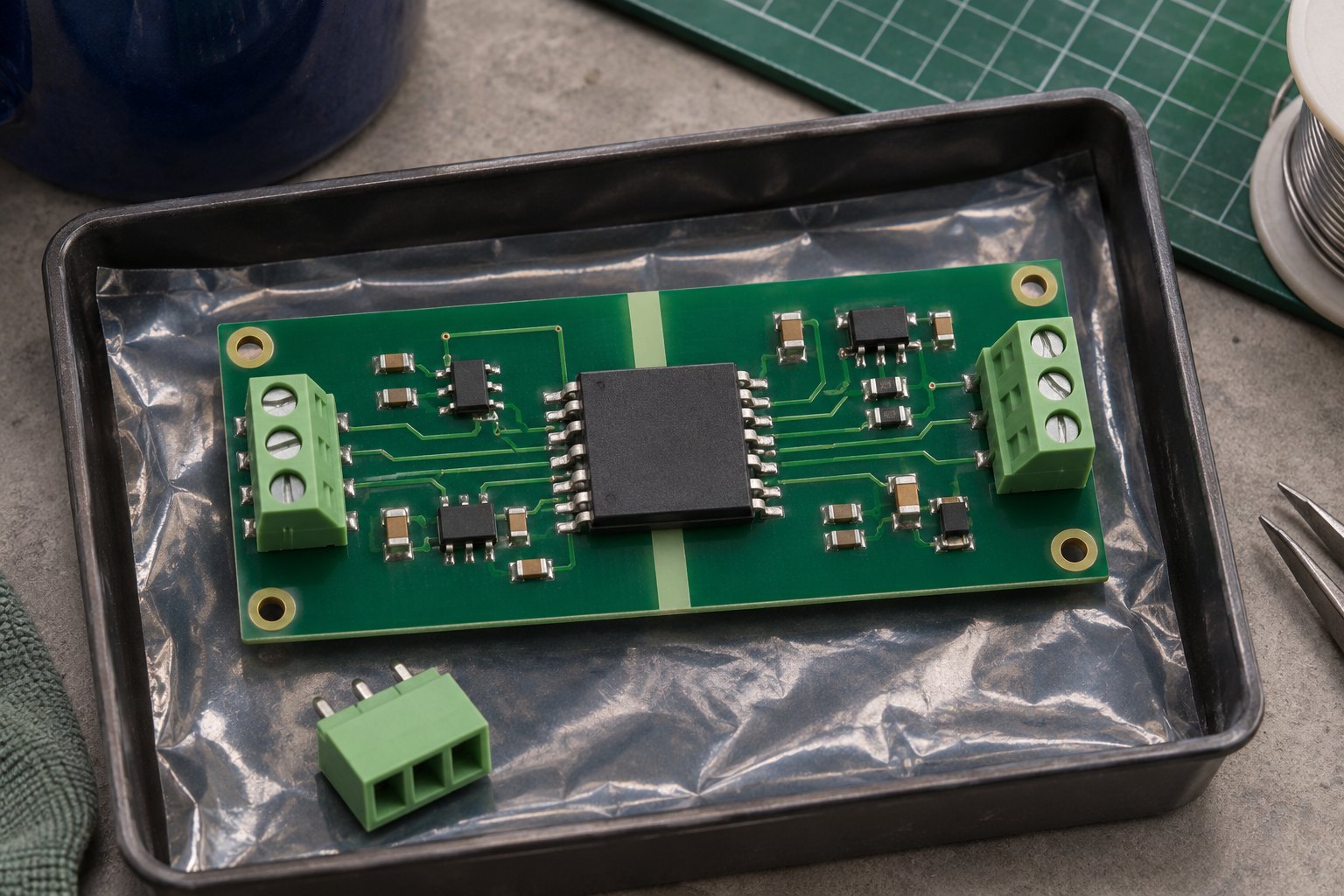
Draw an arrow for each signal on the schematic, then write the source supply, receiving supply, and required inactive level beside it. A statement such as “side 1 is off” is incomplete until the channel direction is known.
Also distinguish a missing supply from a missing command. A powered microcontroller that remains stuck at a valid high level is a different condition from an unpowered transmitter. A default-state option should not be treated as a general monitor of firmware health.
A concrete example: ISO7721 versus ISO7721F
TI’s ISO772x family offers a high-default option without the F suffix and a low-default option with F. The following condensed matrix applies to a channel in that family; it is not a universal table for all digital isolators.
| Input-side supply | Output-side supply | Input condition | ISO7721 | ISO7721F |
|---|---|---|---|---|
| Powered | Powered | Valid high | High | High |
| Powered | Powered | Valid low | Low | Low |
| Powered | Powered | Open | High | Low |
| Powered down | Powered | Irrelevant | High | Low |
| Either state | Powered down | Irrelevant | Undetermined | Undetermined |
In this table, powered means at least 2.25 V within the recommended supply range; powered down means at most 1.7 V. Do not assign a guaranteed logic result to the intervening supply region. The datasheet also warns that driving an input can weakly power a floating supply through a protection diode. Source: ISO772x datasheet, revision G, Table 8-2 and its footnotes.

The engineering consequence is important: an output-side power loss leaves a separate interface-design question to solve. “Undetermined” must remain an unresolved state in the system review until another documented mechanism controls the receiver. It should not be silently changed to zero, one, or high impedance in a spreadsheet.
Use the complete ordering code in the BOM and substitution review. A shortened family name can hide the default-state option as well as package or grade differences.
Choose a default from the receiver’s meaning of high and low
First state the intended inactive action in plain language: keep a driver disabled, keep a peripheral deselected, or hold a processor in reset. Then translate that action through the complete logic path.
| Assumed receiving input | Intended inactive action | Required level at that input |
|---|---|---|
| Enable asserted high | Keep the function disabled | Low |
| Chip select asserted low | Keep the device deselected | High |
| Reset asserted low | Hold the device in reset | Low |
These are illustrative logic definitions. Verify the actual receiver, including any inversion or conditioning between it and the isolator.

For example, suppose an isolator output reaches an active-high enable through an inverter. The receiving enable needs to be low, so the inverter’s input needs to be high. Choosing a low-default isolator simply because “low sounds inactive” would produce the wrong command in that assumed circuit.
Write the result as a traceable requirement:
When the source domain is absent and the receiving domain is valid, the receiving enable shall remain inactive.
Then add the actual voltage thresholds, startup conditions, and timing requirements from the receiver’s documentation. This wording directs the review toward a system behavior that can be observed.
A default state is one part of that behavior. It is not, by itself, a system safety function, a controller watchdog, or evidence that every fault will leave the equipment inactive.
Review the transition, not only the final state
A settled truth table answers what happens after its conditions have been reached. Startup and shutdown also include time spent between those conditions.
Analog Devices documents an approximately 200 µs missing-pulse timeout in its ADuM144x family explanation. That family-specific example shows why the path into a default state needs attention; the figure is not a delay specification for ISO7721 or another unrelated device.
ADI also describes pulses during loss of input-side power for ADuM1200 in a device-specific power-down FAQ. Do not generalize that behavior to every isolator architecture. Use it as a reason to inspect the actual part’s power-transition documentation.

For your design, prepare a sequence review before collecting traces:
| Event to review | What to capture | Question to resolve |
|---|---|---|
| Receiving supply rises first | Both rails, isolated output, receiving command | Does the receiver become active before a valid source exists? |
| Source supply rises first | Source input and receiving startup | Can the receiver accept an unintended initial command? |
| Source supply falls slowly | Rail voltage and output during the ramp | Is the inactive state maintained through the transition? |
| Receiving supply falls first | Output pin and remaining powered interfaces | Are unpowered-pin conditions respected? |
| Brief dip followed by recovery | Rails, reset, output, first valid message | Is operation restarted in a controlled way? |
This is a proposed validation matrix, not a record of completed tests. Set acceptance criteria before testing. If a pulse could trigger the receiver, capture its width and level and compare it with that receiver’s documented response.
Where a command must stay inactive through uncertain intervals, consider an appropriate reset, supervisor, enable, or interlock arrangement. Select that arrangement from the system requirements and verify its own power-loss behavior; adding another component does not remove the need for a sequence review.
Open inputs, pull resistors, and unpowered pins
An open input and a high-impedance output are different conditions at different pins. Neither should be confused with a driven high or low signal.
TI’s digital-isolator design questions advise against leaving unused inputs floating in an application because of noise pickup. The article gives device-specific ways to bias unused inputs and leaves unused outputs unconnected.
For an actively used channel, choose any pull resistor after reviewing the source’s drive capability, input leakage, logic thresholds, and all supply states. A pull on the output does not automatically override an actively driven default. A pull to a rail that disappears first may also fail to provide the intended bias at the critical moment.
A small pull-resistor budget
Consider a hypothetical receiver node that genuinely becomes high impedance, with no active driver opposing its pull-down:
- Pull-down resistance: 10 kΩ.
- Worst-case total current entering the node: 10 µA.
- Receiver’s allowed low-level input voltage: 0.8 V.
The simplified static estimate is:
Vnode = Ileak × R = 10 µA × 10 kΩ = 0.10 V
The corresponding ideal resistance ceiling is 0.8 V / 10 µA = 80 kΩ, before allocating tolerance, noise, or other margin.
This calculation applies only to the stated high-impedance assumption. It does not resolve an undetermined unpowered isolator output or an active output driving high. Replace the assumed leakage and threshold with documented limits for every connected device, including the unpowered condition. If those limits are absent, the calculation is incomplete.
Finally, check whether a still-powered source or pull resistor can drive an unpowered pin beyond its permitted conditions. Review the actual input and output structures, off-state specifications, and recommended interface arrangement. A clean-looking output measured once is not a substitute for those limits.
What to lock into the BOM and substitution review
Record the behavior requirement beside the exact ordering code. This gives purchasing a concrete constraint when a different suffix or family is proposed.

A useful review record contains:
- Signal direction and purpose: source, receiver, active polarity, and any inversion.
- Required inactive behavior: the receiver’s action when either domain is absent.
- Selected part: manufacturer, complete code, package, and document revision.
- State evidence: function table, startup/shutdown information, and unpowered-pin limits.
- Validation status: which sequences have been checked and which remain open.
If an alternative changes the default option, return to the receiver behavior before approving it. Pin arrangement and normal-operation data rate alone cannot answer the power-loss question.
You can start a candidate search in the digital isolator category. When requesting parts through ApexComponent’s inquiry form, include the complete code and the required default behavior, along with quantity and package. Any offered alternative needs application review; the inquiry does not establish stock or compatibility.
For a field-input design using an optocoupler, the 24 V industrial input selection guide explains additional input-current, pull-up, and logic-threshold checks.
Frequently asked questions
Does default low mean the device inverts data?
No. A default option describes a specified fallback condition. Normal-operation polarity comes from the device’s function table.
Is high impedance the same as logic low?
No. High impedance describes a weak or disconnected drive condition. The resulting node voltage depends on the surrounding circuit and leakage.
Will the output default if the controller stops updating it?
Do not assume so. A controller that remains powered and holds a valid input level may continue to command that level. Detecting a stalled controller requires a separate system requirement and suitable monitoring.
Can I replace a high-default part with a low-default version?
Only after checking the resulting receiver action in the required power states and transitions, along with every other substitution requirement.
Sources and method
Prepared on 17 November 2026 from the TI ISO772x datasheet (SLLSEP3G), TI’s digital-isolator design questions, and the two Analog Devices family-specific notes linked above. The sequence matrix, logic examples, and resistor calculation are original editorial guidance using explicitly stated assumptions. No startup, brownout, or power-down testing was performed for this article. Photographic scenes are AI-generated concepts and are not pictures of a qualified product or an actual test result.